Hi there,
This thread prompted me to investigate further, and eventually to develop a basic Rbb tester.
Knowing the overall noise performance of a transistor under certain conditions in a test amplifier does have its usefulness, but being able to evaluate each contribution separately allows a more targeted design approach.
Of the contributing parameters, the base spreading resistance is one of the most important, but it is also one of the most elusive:
The tester I have developed is simplified to the maximum possible, and initially the intention was to make it fully automatic, but things didn't turn out that way: there were too many impossible tradeoffs, and in the end I was left with the choice of an automatic but useless tester, or a working, semi-automatic one.
That is of course the option I chose.
It is not a lab grade instrument, far from that, there are too many simplifications, shortcuts, etc, but it is no toy either: it provides useful indications, particularly for comparison purposes.
The operating principle is simple, as would a straightforwardly derived circuit be, but the devil is in the details, essentially switching ones in this case:
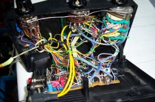
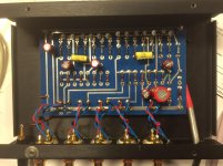
Because of the necessity to accommodate both transistors polarities, to make the current and voltage variable, to handle the functions and decimal points, the result is a nightmare of wiring, selector decks, etc.
I hesitated about the best place to post the subject: after all, it is a test instrument, but one which is going to interest users of discrete semi's, not tubes, chips, etc, which is why I chose the Solid State section.
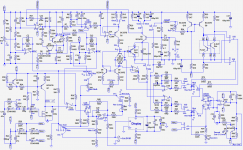
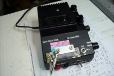
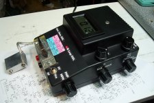
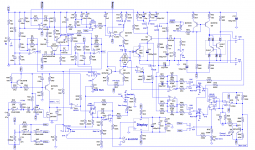
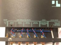
I will describe the circuit later, but here is already the main schematic, and a picture of the finished instrument:
This thread prompted me to investigate further, and eventually to develop a basic Rbb tester.
Knowing the overall noise performance of a transistor under certain conditions in a test amplifier does have its usefulness, but being able to evaluate each contribution separately allows a more targeted design approach.
Of the contributing parameters, the base spreading resistance is one of the most important, but it is also one of the most elusive:
- Only one terminal is accessible
- It is variable, dependent on the transistor's operating conditions
- It has to be measured on the transistor working in its actual circuit
The tester I have developed is simplified to the maximum possible, and initially the intention was to make it fully automatic, but things didn't turn out that way: there were too many impossible tradeoffs, and in the end I was left with the choice of an automatic but useless tester, or a working, semi-automatic one.
That is of course the option I chose.
It is not a lab grade instrument, far from that, there are too many simplifications, shortcuts, etc, but it is no toy either: it provides useful indications, particularly for comparison purposes.
The operating principle is simple, as would a straightforwardly derived circuit be, but the devil is in the details, essentially switching ones in this case:
Because of the necessity to accommodate both transistors polarities, to make the current and voltage variable, to handle the functions and decimal points, the result is a nightmare of wiring, selector decks, etc.
I hesitated about the best place to post the subject: after all, it is a test instrument, but one which is going to interest users of discrete semi's, not tubes, chips, etc, which is why I chose the Solid State section.
I will describe the circuit later, but here is already the main schematic, and a picture of the finished instrument:
Attachments
Presentation
Characteristics:
This tester extracts the Rbb of an NPN or PNP transistor for collector currents varying from 100µA to 10mA, and Vce's of 5V and 2V (it makes almost no difference, but it is also almost free to implement).
Accessorily, it can also measure Ree: that is not the main purpose of the instrument, but since Ree needs to be extracted in the process of measuring Rbb, it can also be displayed.
Operation:
To test a transistor, the process begins by inserting it into the Ree part of the jig.
With the function selector placed on "Ree Null Comp", the nulling potentiometer is used to zero the reading on the display.
If desired, the Ree value can be read on the "Ree" position, then the transistor is moved to the Rbb section, as is the function selector.
The isothermal cap is placed, and when the reading has settled, the Rbb value is displayed.
Once the initial compensation has been made for a given transistor, the collector current and the Vce can be freely varied, without any further adjustment.
The average Ic can also be displayed on the corresponding position of the selector.
Principle of operation:
With the transistor under test properly biased (I will detail this later), its BE junction is placed in a bridge: the TUT and a reference junction Q3 or Q4 form one arm of the bridge, the other being R59 and R60.
The base current is pulsed at ~70Hz, with a ratio between the highs and lows of approximately e, yielding a voltage variation of ~25mV on both junctions.
The reference junction is a diode-connected transistor, selected for its low Ree and Rbb, and high beta down to low currents, meaning its behavior obeys almost perfectly the ideal logarithmic law, unlike the TUT.
The small imbalance caused by the series resistances of the TUT will generate a voltage across the bridge.
This voltage contains the Rbb*Ib information, but also the Ree*β*Ib term, which has to be eliminated.
That is the role of the Ree jig:
The Ree is measured by pulsing the base current of the TUT in a deep saturation condition, and sampling the resulting variation of the Vce.
This value cannot be subtracted directly from the raw Rbb voltage: there is the β factor between them, or in other words, the Rbb is referred to Ib but Ree is referred to Ie~=Ic.
The Ree voltage is thus used to set the position of a potentiometer fed by a fixed reference voltage, and when the actual Rbb measurement is made, the feeding voltage is switched to a voltage representative of Ic.
The potentiometer thus serves as a storing register and as a multiplier.
The same could be achieved completely automatically with a microcontroller and a good quantity of relay contacts.
Once the Ree term has been eliminated, the half-raw result still needs to be scaled according to Ib, to fulfill the Rbb=Vb/Ib relation.
The final result of these operations can then be displayed, and reflects the pure Rbb value.
Since the circuit heavily relies on thermal voltages for compensation, the TUT and the reference junction need to be kept at exactly the same temperature, which is why an isothermal box is required.
Rbb tester - Great!!!
Wow!!! another very interesting project as always LV
MC phono preamp's fanatics will probably wake up soon to discover this rare instrument.
Do you have for us some of your results of the Black Knight tests on some known devices like the ZTX690?
Does this instrument will reveal that the 2N4401 / 2N4403 are more famous than we thought already?
Not yet, but be sure that I will test a large number of devices and share the results.Do you have for us some of your results of the Black Knight tests on some known devices like the ZTX690?
Does this instrument will reveal that the 2N4401 / 2N4403 are more famous than we thought already?
In the first tests (testing the instrument more than devices themselves), surprising results have already emerged: for example, not all BC550 are created equal, there are significant differences between manufacturers.
For now, as some unexpected issues have emerged in the final version, the thread will stay on the back-burner until I have cleared everything.
I should be back in a few days....
they don't make analog designers like you anymore elvee
Here is the updated schematic. I will detail later what the issues were.
Now, let's have a look at the base current controller.
Its role is to convert the Ic potentiometer setting into the corresponding, properly modulated base current.
This requires a servo loop, because the beta of the T.U.T. is unknown.
The servo controller is U1B: it is a LM393 operator used as an opamp.
It compares the +7.5V-referenced Ic setting to the average collector current measured by R14 or R15, filtered by C8 or C9.
The cascode transistor Q2 sets the Vce of the T.U.T.
U2A/Q1 actually do the job of generating the base current, modulated by U4A to a ratio of ~1:2.718.
U2B and U3A generate ground-referenced versions of the voltages representative of Ic and Ib, used for display and processing.
The circuit is natively designed for NPN transistors, and the adaptation to PNP's is performed by mirroring the base current with Q5/Q6, and reversing the C and E of the T.U.T.
The loop can accommodate β-values in the 60 to 1200 range.
If those limits are exceeded (or if the T.U.T. is faulty or misconnected), Q11 or Q12 detects the condition and lights the warning LED D3.
The generated Ib also flows through the reference junctions, Q3 or Q4.
Attachments
Last edited:
Amplifier, synchronous demodulator and Ree section
Amplifier:
The base current generated by Q1 or mirrored by Q5 is applied to the reference junction and the BE of the T.U.T., forming one arm of the measuring bridge.
The other arm (driven by the buffer U3B) is formed by R59 and R60, which are matched very accurately.
If both the reference junction and the T.U.T. ideally obey the logarithmic law, the two arms will generate a step of exactly 26mV, and the difference sensed and amplified by U2C and U2D will be zero.
Because Q3 and Q4 are diode-connected and selected for a good ideality, any difference will be caused by the imperfections of the T.U.T. and will appear between the outputs of the diff-amp.
Synchronous demodulator:
The difference voltage is fed to the common of the analog switches, which alternate between the + and - inputs of the difference amplifier/integrator.
The clock driving the switches is the same as the one that drives the bi-level base current, making the circuit completely insensitive to external perturbations (within reason), DC offsets or common mode voltage: the output of U3D is an accurate image of the voltage difference between the two levels, and nothing else.
This raw voltage will need further processing, because it contains other terms and constants than the pure Rbb.
Ree Meter:
The Ree meter uses globally the same strategy and detector as the Ib generator, but it can be made simpler, because the current is fixed.
The test current is generated by Q9 and Q10, and applied to the base of the T.U.T., which is driven into deep saturation. Since under those conditions, the C-E space is more or less a short, the voltage appearing at the collector will be an image of the voltage on the internal emitter, after the Ree; that's the theory anyway, because in reality, things are not that clean and there is also a residual internal Vce voltage, and the Ree itself has some disconcerting properties when viewed from a "compact model" perspective.
That is the reason for R57 and R58, and the difficulties I have encountered: because the final Rbb result involves a subtraction between the raw voltage and a Rbb-related one, any tiny inaccuracy in any of the terms has a disproportionate effect on the accuracy of the final result.
The surest way to blow measurement uncertainties is to subtract two very similar quantities, which can be the case here, but is unfortunately unavoidable.
The PNP jig looks different, but in fact works in exactly the same way, as the perfect CMR of the sync-dem allows the sampling across the C and E.
Some test results:
I have begun systematic tests, starting with the BC549/50 family (Ic=2mA, Vce=2V):
Some interesting differences are already apparent...
Amplifier:
The base current generated by Q1 or mirrored by Q5 is applied to the reference junction and the BE of the T.U.T., forming one arm of the measuring bridge.
The other arm (driven by the buffer U3B) is formed by R59 and R60, which are matched very accurately.
If both the reference junction and the T.U.T. ideally obey the logarithmic law, the two arms will generate a step of exactly 26mV, and the difference sensed and amplified by U2C and U2D will be zero.
Because Q3 and Q4 are diode-connected and selected for a good ideality, any difference will be caused by the imperfections of the T.U.T. and will appear between the outputs of the diff-amp.
Synchronous demodulator:
The difference voltage is fed to the common of the analog switches, which alternate between the + and - inputs of the difference amplifier/integrator.
The clock driving the switches is the same as the one that drives the bi-level base current, making the circuit completely insensitive to external perturbations (within reason), DC offsets or common mode voltage: the output of U3D is an accurate image of the voltage difference between the two levels, and nothing else.
This raw voltage will need further processing, because it contains other terms and constants than the pure Rbb.
Ree Meter:
The Ree meter uses globally the same strategy and detector as the Ib generator, but it can be made simpler, because the current is fixed.
The test current is generated by Q9 and Q10, and applied to the base of the T.U.T., which is driven into deep saturation. Since under those conditions, the C-E space is more or less a short, the voltage appearing at the collector will be an image of the voltage on the internal emitter, after the Ree; that's the theory anyway, because in reality, things are not that clean and there is also a residual internal Vce voltage, and the Ree itself has some disconcerting properties when viewed from a "compact model" perspective.
That is the reason for R57 and R58, and the difficulties I have encountered: because the final Rbb result involves a subtraction between the raw voltage and a Rbb-related one, any tiny inaccuracy in any of the terms has a disproportionate effect on the accuracy of the final result.
The surest way to blow measurement uncertainties is to subtract two very similar quantities, which can be the case here, but is unfortunately unavoidable.
The PNP jig looks different, but in fact works in exactly the same way, as the perfect CMR of the sync-dem allows the sampling across the C and E.
Some test results:
I have begun systematic tests, starting with the BC549/50 family (Ic=2mA, Vce=2V):
Code:
Type        Mfr    Prod. year    Ree      Rbb

BC549C      Phil    1980         0.85     430
BC550C      Phil    ~2000        0.72     234
BC550       Siem    ~1995        0.98     247
BC550B      MultiC   ~2000       0.57     >650
BC550C      Moto    1998         0.43     73
BC550       NS      1995         0.29     62
BC439       Hita    ~1980        0.71     >650
Some interesting differences are already apparent...
Processing:
Before displaying the final result, some arithmetics have to be applied to the raw demodulated voltage:
The first step is to correctly position the compensation potentiometer.
When the instrument is in "Null Comp" mode, the signal is passed through U3C without modification: U3C performs the base current hyperbolic correction (more on this later), but when no device is plugged into the Rbb section, the Ib loop is in positive saturation, making the switch U4B permanently closed.
Thus, the raw signal appears unchanged (except for the sign) at the output of U3C and is applied to one side of the resistive bridge R44-R45.
The other side receives the output of the compensation potentiometer, fed by a suitably scaled voltage of opposite polarity.
The output of the bridge is monitored, and when the null is reached, the potentiometer is correctly positioned to subtract the Ree*Ic term from the raw Rbb*Ib + Ree*Ic voltage when the function selector is moved to Rbb, and the Ic-dependent correction is applied through R41-R42.
Now that the output of U3C only depends on Rbb*Ib, the last thing that remains to be done to display Rbb is the division by Ib:
The DC gain of U3C is set by the ratio of R40 to R70, multiplied by the inverse of the duty cycle of U4B.
U4B is controlled by the the comparator U1A. A sawtooth is applied to its reference input, while a voltage representing the base current is applied to the other.
The duty cycle at its output is thus an exact image of the base current.
The sawtooth has a frequency of 400Hz, and the amplifier is filtered by C20, to make R40/d look like a real, continuous resistor.
Now, some results for typical "low noise" PNP transistors, also @ 2mA & 2V:
Before displaying the final result, some arithmetics have to be applied to the raw demodulated voltage:
The first step is to correctly position the compensation potentiometer.
When the instrument is in "Null Comp" mode, the signal is passed through U3C without modification: U3C performs the base current hyperbolic correction (more on this later), but when no device is plugged into the Rbb section, the Ib loop is in positive saturation, making the switch U4B permanently closed.
Thus, the raw signal appears unchanged (except for the sign) at the output of U3C and is applied to one side of the resistive bridge R44-R45.
The other side receives the output of the compensation potentiometer, fed by a suitably scaled voltage of opposite polarity.
The output of the bridge is monitored, and when the null is reached, the potentiometer is correctly positioned to subtract the Ree*Ic term from the raw Rbb*Ib + Ree*Ic voltage when the function selector is moved to Rbb, and the Ic-dependent correction is applied through R41-R42.
Now that the output of U3C only depends on Rbb*Ib, the last thing that remains to be done to display Rbb is the division by Ib:
The DC gain of U3C is set by the ratio of R40 to R70, multiplied by the inverse of the duty cycle of U4B.
U4B is controlled by the the comparator U1A. A sawtooth is applied to its reference input, while a voltage representing the base current is applied to the other.
The duty cycle at its output is thus an exact image of the base current.
The sawtooth has a frequency of 400Hz, and the amplifier is filtered by C20, to make R40/d look like a real, continuous resistor.
- Note that this step is much more than a mere correction, and needs to be carried out accurately for a wide dynamic range: the tester accomodates β values in a 1:20 ratio and Ic currents in >1:10 ratio, meaning a total dynamic range of ~50dB.
Now, some results for typical "low noise" PNP transistors, also @ 2mA & 2V:
Code:
Type        Mfr    Prod. year    Ree      Rbb

BC559B      Phil    1979         0.90     58
BC559B      Phil    1996         0.49     54
BC154       SGS     1969         0.10     341
BC154       NS      1973         0.52     428
2SA852      Mitsu   ~1980        0.19     81
BCY79VII    Sie     1976         <0.1     265
BC320B      Fair    ~1980        0.40     244
BC558B TFK ~1980 0.14 133No, I am afraid I haven't. They are a bit out of the ordinary BTW: 5A in a TO39 case is rather uncommon.Simply outstanding. Have you any BC323/333 samples to measure?
I think I may have something similar though: 2N5339. I'll have to check
No, I am afraid I haven't. They are a bit out of the ordinary BTW: 5A in a TO39 case is rather uncommon.
I think I may have something similar though: 2N5339. I'll have to check
Hi Elvee,
Sorry for my mistake, I meant to ask BC327 and BC337.
If you PM me your shipping address, I would be glad to send you a few samples of the lowest Rbb transistors that Horowitz and Hill measured, in their 2015 survey of 54 different BJTs (Art of Electronics, 3rd edition, p.501). I'll also toss in a couple of MPS6571s; these are the NPNs that Nelson Pass used in the Threshold M1 moving coil pre-preamp, and that he also used in the Threshold NS10 preamplifier phonostage and line amp stage. Datasheet attached.
_
_
Attachments
Last edited:
I'll also toss in a couple of MPS6571s; these are the NPNs that Nelson Pass used in the Threshold M1 moving coil pre-preamp, and that he also used in the Threshold NS10 preamplifier phonostage and line amp stage. Datasheet attached.
_
These look very unspecial for noise? Just under 4nV at any Ic for Rs = 0.
Go back in time to 1978 and visit Mr. Nelson Pass in Sacramento California. Tell him he's making a not-so-great choice.These look very unspecial for noise? Just under 4nV at any Ic for Rs = 0.
Go back in time to 1978 and visit Mr. Nelson Pass in Sacramento California. Tell him he's making a not-so-great choice.
Did you read/verify the data sheet, maybe it lies? Then you could tell John Curl when he "discovered" the 2N4401/4403 he was wrong.
Yikes you have deduced my sinister plan! Everything hinges upon Elvee testing the MPS6571s and finding them superior.Did you read/verify the data sheet, maybe it lies? Then you could tell John Curl when he "discovered" the 2N4401/4403 he was wrong.
- Status
- This old topic is closed. If you want to reopen this topic, contact a moderator using the "Report Post" button.
- Home
- Amplifiers
- Solid State
- An (almost) Automatic Rbb Extractor: the Black Knight