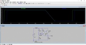
The zener gives us more control, allowing more voltage of the exponential charging voltage that appears across the cap to be used. If we remove the zener from the darlington arrangement then we need a much bigger cap to get a decent delay. Also the relay doesn't drop out before the rails collapse (although of course the relay itself will drop out as the current falls below the holding value. So it might still be workable).
The FET has the big advantage of already having a turn on voltage of around 4 volts (Vgs) so that goes a long way to making up for no zener. Same thing for the relay applies. It will drop out as the rails fall.
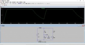
The red trace for the FET is Vg. Just checking it was within limits.
So slight tweak of values.
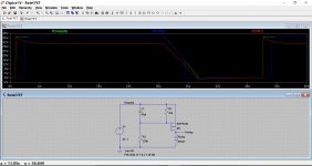
The FET has the big advantage of already having a turn on voltage of around 4 volts (Vgs) so that goes a long way to making up for no zener. Same thing for the relay applies. It will drop out as the rails fall.
The red trace for the FET is Vg. Just checking it was within limits.
So slight tweak of values.
Attachments
Oh actually it need not be polarised because once it's charged no current will conduct to ground. Cap doesn't conduct DC! It behaves like an open circuit, not a short. Ah it's all coming back to me now.
So basically while the cap is charging, it's starving the emitter of the transistor (path of least resistance) until it's charged, once it's charged, it doesn't conduct DC so the current has only one path to go, through the transistor. Is this correct?
Still not sure how the zener diode works here, but I'll take your word for it at this stage.
Look at this. A quick re-arrangement to make it easier to follow. First picture shows the cap charging/discharging voltage as the amp is switched on and off.
Imagine we want to control an NPN transistor to switch a relay or bulb as in the second diagram. The transistor will turn on when the voltage has reached only 0.7 volts or so. We are not making use of the full extent of the 'curve'. This also means we need a massive cap to get a suitable time delay. Again we are looking at the cap voltage. So its clamped at 0.7 v by the transistor.
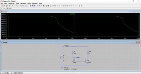
Adding a zener allows us to pick a point on the curve where we want the transistor to turn on. If we choose a 12 volts zener then nothing happens until the voltage has reached 12v plus 0.7 vbe of the transistor.
Now add a zener.
The zener also helps with turn off. It allows the transistor to drop out when the voltage drops below the zener voltage.
Imagine we want to control an NPN transistor to switch a relay or bulb as in the second diagram. The transistor will turn on when the voltage has reached only 0.7 volts or so. We are not making use of the full extent of the 'curve'. This also means we need a massive cap to get a suitable time delay. Again we are looking at the cap voltage. So its clamped at 0.7 v by the transistor.
Adding a zener allows us to pick a point on the curve where we want the transistor to turn on. If we choose a 12 volts zener then nothing happens until the voltage has reached 12v plus 0.7 vbe of the transistor.
Now add a zener.
The zener also helps with turn off. It allows the transistor to drop out when the voltage drops below the zener voltage.
Attachments
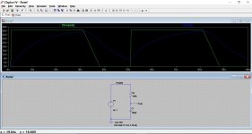
Look at this. A quick re-arrangement to make it easier to follow. First picture shows the cap charging/discharging voltage as the amp is switched on and off.
Imagine we want to control an NPN transistor to switch a relay or bulb as in the second diagram. The transistor will turn on when the voltage has reached only 0.7 volts or so. We are not making use of the full extent of the 'curve'. This also means we need a massive cap to get a suitable time delay. Again we are looking at the cap voltage. So its clamped at 0.7 v by the transistor.
Adding a zener allows us to pick a point on the curve where we want the transistor to turn on. If we choose a 12 volts zener then nothing happens until the voltage has reached 12v plus 0.7 vbe of the transistor.
Now add a zener.
The zener also helps with turn off. It allows the transistor to drop out when the voltage drops below the zener voltage.
Awesome, I think I understand it. Thanks so much for the help.
- Status
- This old topic is closed. If you want to reopen this topic, contact a moderator using the "Report Post" button.