Hi all,
Just looking to see if anyone here has had any experience with Silicon Chip's latest version Ultra-Low Distortion Amplifier (Mk4) from the second half of last year? It uses SMD components extensively and has some pretty impressive distortion figures.
Has anyone had any experience with this revised design or has seen the article and has any thoughts on the design?
From what I can see it is based quite heavily on the "Blameless" design from Doug Self however there are a few subtle differences here and there plus the use of the Thermal Trak transistors and SMD components.
I've done quite a bit of googling but I can't seem to find any feedback on this latest version - plenty on the Mk3. I can only think that perhaps the SMD design has turned many DIYers away from it or perhaps the fact that no one is selling a complete kit.
None the less, interested to hear peoples thoughts before I embark on building some.
P.S. Go easy - I'm new here.
All silicon chip did is what I'm about to do.
- They SMD'ed the differential , cascodes , and mirror (plus CCS).
- Mtz796/696 for VAS ..... inferior to KSA1381/SC3503.
Still have to use up several square CM PCB to sink the D-PAK mtz's.
They will get lower noise , better matching at the first stages ....
but , drive a slightly inferior voltage stage.
They could of saved a lot of space with SMD , they still use the same
huge board.
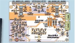
Looking at the layout (below).
Nothing groundbreaking ,
- They are using TMC (15p + 150p + 2.2k).
- Main CCS's are unified with the red LED ( I stopped using this before the badger).
- No interleaved P/N/P/N output configuration.
Why did they not go all the way ? I mean with SMD and all that board space -
solid state output relays , DC protect , and a servo to replace that 1000uf and trimmer ?
OS
- They SMD'ed the differential , cascodes , and mirror (plus CCS).
- Mtz796/696 for VAS ..... inferior to KSA1381/SC3503.
Still have to use up several square CM PCB to sink the D-PAK mtz's.
They will get lower noise , better matching at the first stages ....
but , drive a slightly inferior voltage stage.
They could of saved a lot of space with SMD , they still use the same
huge board.
Looking at the layout (below).
Nothing groundbreaking ,
- They are using TMC (15p + 150p + 2.2k).
- Main CCS's are unified with the red LED ( I stopped using this before the badger).
- No interleaved P/N/P/N output configuration.
Why did they not go all the way ? I mean with SMD and all that board space -
solid state output relays , DC protect , and a servo to replace that 1000uf and trimmer ?
OS
Attachments
Did not mean to denigrate Silicon Chip's design. But , after
4 revisions and the jump to SMD .... it should have many more
features and refinements.
As it is , it will match a Badger - that's it. (EF2 , TMC).
Won't match a Wolverine (EF3 plus better TMC , CCS's).
Can't ever match my new SMD creations with servo's , DC protect
and other "extra's".
OS
4 revisions and the jump to SMD .... it should have many more
features and refinements.
As it is , it will match a Badger - that's it. (EF2 , TMC).
Won't match a Wolverine (EF3 plus better TMC , CCS's).
Can't ever match my new SMD creations with servo's , DC protect
and other "extra's".
OS
Thanks for your feedback OS.
I'm interested to understand further some of the points you have made.
What exactly is inferior about the VAS transistors SC selected?
Looking at the circuit diagram the only LED I can see relating to the CCS's is in the current path for the input differential pair. Is this the one your referring to? What is the issue with it's use and could you replace it with a suitably sized resistor or similar to negate the issue?
What is the advantage of interleaving the outputs? This is new to me.
I agree I'm not a fan of the trimmer in the differential pair to adjust the offset. A more advanced DC servo would have been nice given the PCB space available as you have pointed out. Perhaps SOA limiting as well.
They have however produced a separate Speaker Protection circuit PCB using SMD components also. This came in the Nov '15 edition of the mag.
Although slightly off-topic, but in reference to your designs that you have mentioned and/or others, can you recommend any other kit-amps that would likely have better performance? Unfortunately I don't have enough time to prototype my own amp and design the PCB (cherish the thought...) so I'm limited to looking for PCB's which are already designed that I can build.
Thanks for your feedback OS.
I'm interested to understand further some of the points you have made.
1 -What exactly is inferior about the VAS transistors SC selected?
2- Looking at the circuit diagram the only LED I can see relating to the CCS's is in the current path for the input differential pair. Is this the one your referring to? What is the issue with it's use and could you replace it with a suitably sized resistor or similar to negate the issue?
3-What is the advantage of interleaving the outputs? This is new to me.
MK4 looks like a good kit - If it is a derivative of the MK3 plus TMC -
exceptional.
1- those Mtz796/696 are not bad , but have higher Cob and can't dissipate
like TO-126. 2W versus 7W for the sc3503/sa1381 pair.
On an EF2 (like the MK4) , 7-10ma is needed to negate the VAS loading
and associated "droop" of the EF2 with higher loading.
The MTZ's would be great for an EF3 (triple EF) running at 4-5ma.
Even the Badgers TO-126 devices get pretty warm at 7+ma.
2- If that's true and the LED is not a CCS reference , but in-line with the
differential - who knows what improvement (or for what purpose) it serves.
The MK3 uses a standard 2Q CCS at the VAS .... referencing the LTP , also.
This CCS setup , along with no diode or transistor overload clamp - means ...
don't clip any of these kits.
It seems , Silicon chip just added a clip indicator instead of actually controlling it.

3- ahh , interleaving the outputs on a double sided PCB ....
Do this , and high current inductive noise is cancelled.
Silicon chip did not do too bad with short paths , but they still fall short
of the type and level of the forums PCB star grounding techniques.
At least they kept the high current paths away from the input stage.
PS - the interleaving and these more advanced tricks can be seen on 10K$
Pass amps - Parasound , etc.
Edit - do we actually have a MK4 schema ?
OS
Last edited:
- Status
- This old topic is closed. If you want to reopen this topic, contact a moderator using the "Report Post" button.
- Home
- Amplifiers
- Solid State
- Silicon Chip ULD Amp Mk4