HI alls,
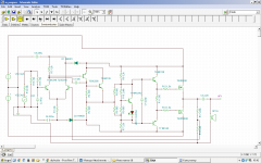
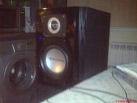
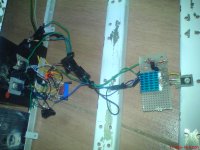
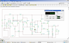
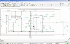
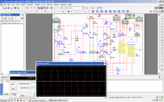
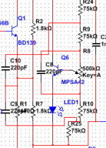
here are the sch, analyses and pics of the build.
it sounds good, clear, hifi.
When its warm gate-gate bias voltage goes up with 100mV.
I designed the sch for +-35V but i have +-34 when playing music.
Is it better to design for +-34 ?
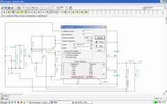
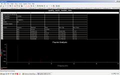
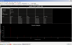
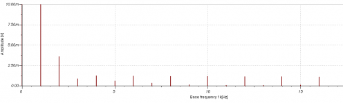
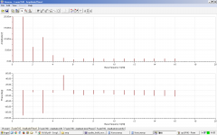
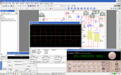
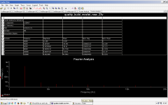
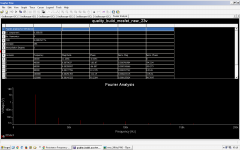
There are two Multisim harmonics analyses because the worse one is with 7ma bias current instead 86mA@35V supply voltage. In one of the screenshots there are 30-40mA because supply voltage there is 34.5V instead 35.
I tested with 7ma because to come close to reality.
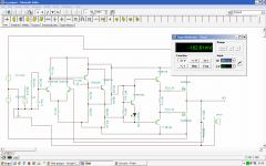
i measured 200mv offset in reality where in Multisim is only 16mV.
I divided 200mv/16mv and there are 12.5 difference.
This means 86mA/12.5 -> 7mA 😀
i found out its 200mv in TINA too, this means TINA is more close to reality and actually its very close 🙂
here are the sch, analyses and pics of the build.
it sounds good, clear, hifi.
When its warm gate-gate bias voltage goes up with 100mV.
I designed the sch for +-35V but i have +-34 when playing music.
Is it better to design for +-34 ?
There are two Multisim harmonics analyses because the worse one is with 7ma bias current instead 86mA@35V supply voltage. In one of the screenshots there are 30-40mA because supply voltage there is 34.5V instead 35.
I tested with 7ma because to come close to reality.
i measured 200mv offset in reality where in Multisim is only 16mV.
I divided 200mv/16mv and there are 12.5 difference.
This means 86mA/12.5 -> 7mA 😀
i found out its 200mv in TINA too, this means TINA is more close to reality and actually its very close 🙂
Attachments
-
 sch.PNG69.1 KB · Views: 575
 -
 ms_offset.PNG26.4 KB · Views: 186
 -
 offset.PNG69.5 KB · Views: 135
 -
 square.PNG43.9 KB · Views: 121
 -
 THD.PNG69.8 KB · Views: 115
 -
 86mA.PNG54.3 KB · Views: 98
 -
 7mA.PNG54.3 KB · Views: 409
 -
 DSC05676.JPG494.2 KB · Views: 422
 -
 DSC05669.JPG437.4 KB · Views: 475
 -
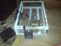 DSC05677.JPG525.5 KB · Views: 542
Last edited:
Here are the multisim and tina files 🙂
NOTE!!!->I added to them .asc extensions to can upload as attachments.
(gives me invalid file error).
NOTE!!!->I added to them .asc extensions to can upload as attachments.
(gives me invalid file error).
Attachments


Last edited:
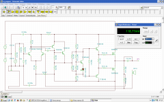
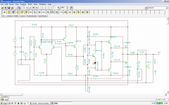
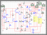
R11 is 220ohm in multisim's screenshot because i was measuring how many watts i can get at 220 ohm 😀 Analyses are normal with 4 or 6 ohm load. i forgot what i tested. 4 or 6 .
I want to mention that firstly i tested with beta-enhanced VAS (collector to ground) but it gives poor results comparing to this.
maybe i need 2n5401 instead bc556 but thats why i added 33k series to input to limit the signal not getting too high.
I want to mention that firstly i tested with beta-enhanced VAS (collector to ground) but it gives poor results comparing to this.
maybe i need 2n5401 instead bc556 but thats why i added 33k series to input to limit the signal not getting too high.
Attachments

Last edited:
I dont like the way to drive OPS with one transistor upside or down.
I like to "inject" the signal in the middle.
I think this is very big mistake in every amp !
P.S. I noticed that 1n4001 diodes must be replaced with 47 ohm resistors becase the distortion is very worse with them.
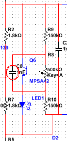
P.S.2. Forgot to mention that R10 is 560+5k trim pot for full range bias tuning (2Vto4)
P.S.3. With 750 instead 440 ohm is better with less Pd for bd139. this R must be 5W.
Im using 440 because the only powerful resistors i have are 220ohm. They are 5W and im using them in series. It cooks them very well 😀
P.S.4. I am dreaming for that black tea in my prev post that im not having now 🙁 Here are only crappy tea I dont like. My parents have bad taste I like but very little.
P.S.5. Moderator, add one "(beginner starts here)" to the thread heading, name. Or "(perfect for beginners)".
I like to "inject" the signal in the middle.
I think this is very big mistake in every amp !
P.S. I noticed that 1n4001 diodes must be replaced with 47 ohm resistors becase the distortion is very worse with them.
P.S.2. Forgot to mention that R10 is 560+5k trim pot for full range bias tuning (2Vto4)
P.S.3. With 750 instead 440 ohm is better with less Pd for bd139. this R must be 5W.
Im using 440 because the only powerful resistors i have are 220ohm. They are 5W and im using them in series. It cooks them very well 😀
P.S.4. I am dreaming for that black tea in my prev post that im not having now 🙁 Here are only crappy tea I dont like. My parents have bad taste I like but very little.
P.S.5. Moderator, add one "(beginner starts here)" to the thread heading, name. Or "(perfect for beginners)".
Last edited:
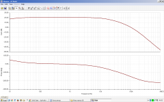
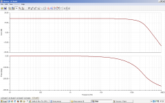
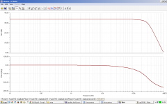
Forgot AC transfer
P.S. From now i will design for 5ohm load because min is 2ohm, max is 8 and AVG(2,8) = 5 ;p
P.S.2 Im going to redesign this because the transformer in the case is 4*17.5VAC 250W (im powering this with external one).
I will use only 2*17.5AC ->2*22DC. This would give me 20/5*20 -> 2x80W peak power @5ohm which satisfies my needs 🙂
Attachments

Last edited:
Updated sch -> R3 is now 2k & R1 is now 33k
this gives 119mv offset with these 47R resistors for filtering 🙂
i will add fuse between mosfet sources and FB.
in TINA there are no fuses 😱
Oh i need to do new analyses in TINA because i analysed with 34.5V insted 35 and thus lower the bias to 30-40mA instead ~90mA
I need to retune the biasing, now im designing this for 34V.
Attachments
Last edited:
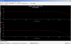
when i bypass C3 i get better AC analys.
I changed R10 to 2.88k to get 86mA with +-34V but im confused why can't measure that. Look i added 0.47 resistor to measure the current but there are only 36uV instead 40mV 😕
And i was mistaken the offset voltage because i was measuring with signal 😀
i said 100-200mV, without signal its 37mV ! even better ;p
Attachments
I think using CCS is very bad idea.
It makes no sense and even worse -> worse thermal stability.
Its floating resistance. Tail current must be stable, not termo dependable 😉
It makes no sense and even worse -> worse thermal stability.
Its floating resistance. Tail current must be stable, not termo dependable 😉


T5 must be 2n5401 for the bootstap improvement.
And one pair of mosfets is not enough. There must has paralleling.
And one pair of mosfets is not enough. There must has paralleling.
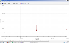
Updated sch and new analyses ->
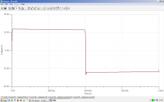
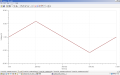
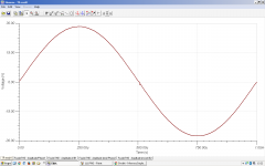
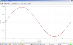
square 1khz, square 20khz, sine 1khz and sine 20khz
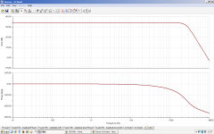
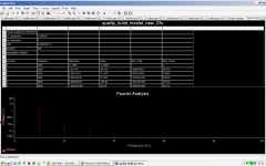
harmonic dist - 0.1% 1khz ; 2% 20khz
square 1khz, square 20khz, sine 1khz and sine 20khz
harmonic dist - 0.1% 1khz ; 2% 20khz
Attachments


Last edited:
i dont care, itsounds good.
one thing missing -> dc speaker protection
and i will stop with this becauuse i dont have such a powerful transformer or smps.
i will design it with bc556 instead 2n5401 and +-22V which is perfect for 1pair of mosfets and 260W trafo.
beta enchanced vas doesnt work for me since it gives worser results
(transistor to ground)
Last edited:
this distortion gets lower with 22p compensation but is this enough ?
If you send me your Multisim file, I will show you the stability margins, possible issues, etc. I just don't want to re-draw the whole thing.
vzaichenko@gmail.com
Files are in post #2 but i sent you the new version (23.4V one). Im uploading it here too just need to be renamed from .ms12.asc to .ms12
I measured 23.7V but im designing it for 23.4 (for high volumes).
I have very good idea -> to add shunting capacitor across R10.
this will short R10 @ 20khz -> more bias current from 94mA it goes to 378mA. Its possible to be even more,
this means class A at high frequencies 😀 😉

This is very good idea ;p
p.s. with rc filter calculator i calculated C2 to be 1n. Its 220p because i dont have 1n.
I measured 23.7V but im designing it for 23.4 (for high volumes).
I have very good idea -> to add shunting capacitor across R10.
this will short R10 @ 20khz -> more bias current from 94mA it goes to 378mA. Its possible to be even more,
this means class A at high frequencies 😀 😉
This is very good idea ;p
p.s. with rc filter calculator i calculated C2 to be 1n. Its 220p because i dont have 1n.
Attachments
Last edited:
I calculated that 10u is needed for the good idea and tested it but its not working ? When i short circuit there its working dropping 20khz distortion to 0.2% which is very good. with the capacitor its 0.6% 🙁
I found out its better to use low value stoppers instead 1k5
i was calculated them with rc filter calculator and the capacitor inside to source.
P>S. Now with 220r stoppers im getting 0.12% @ 20khz & 0.1% @ 20khz with short across R10.
Maybe im not needing this idea no more 😀
I found out its better to use low value stoppers instead 1k5
i was calculated them with rc filter calculator and the capacitor inside to source.
P>S. Now with 220r stoppers im getting 0.12% @ 20khz & 0.1% @ 20khz with short across R10.
Maybe im not needing this idea no more 😀
Attachments
Last edited:

i improved it bootstrapping the vbe, never seen technique before 😀
but is it worth ?
i very like the idea to be class A in 20khz but must think about it how to implement.
what bias current is needed for class A operation ?
Also i know how to improve this bootstrapped VBE allowing more bias current.
Changing the 1.8kiloohms to 2.4k and vbe's resistances. this will allow more bias current in the booting
P.S. this fourier is again @ 20 khz
Attachments
Last edited:
- Status
- Not open for further replies.
- Home
- Amplifiers
- Solid State
- IRF530/9530 Amplifier (simulated in Multisim and TINA)