
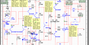
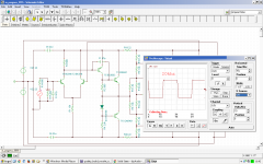
Ultimate front-end, discrete op-amp, different transistors because i didnt have enough from BCs ")
im little confused because in TINA R3 is 5.6k,6.8k unlike here -> 680,1k
And R5 == 1,1.5k in TINA (2k4,3k in Multisim).
I tried it reallife but Q5 blowed, why ? I tried with R3 = 4k7 and R5 = 2k4.
im little confused because in TINA R3 is 5.6k,6.8k unlike here -> 680,1k
And R5 == 1,1.5k in TINA (2k4,3k in Multisim).
I tried it reallife but Q5 blowed, why ? I tried with R3 = 4k7 and R5 = 2k4.
Attachments
Last edited:
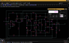
Last version is perfect !!!!
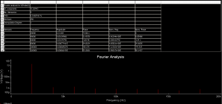
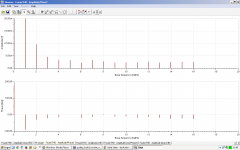
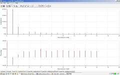
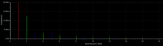
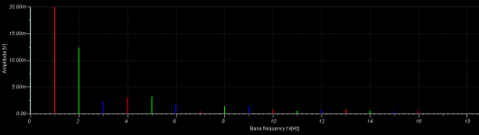
there are 2 ffts attached, at 1khz and at 20khz.
there are two versions, bjt inputed and mosfet inputed.
mosfet input one is better because it has only 200mv offset without need of biasing the input.
bjt one has -5.4V offset and need some megaohms in the input to + or to 1st ltp collector.
i am using capacitor for dc speaker protection, but this is for now, i am not a ninja ;d
And yes here absolutely no difference between Multisim and TINA :O
same currents
P.s. the local fb near R2 does big magic and job !
Attachments
Last edited:
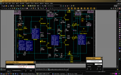
Ultimate front-end, discrete op-amp, different transistors because i didnt have enough from BCs
im little confused because in TINA R3 is 5.6k,6.8k unlike here -> 680,1k
And R5 == 1,1.5k in TINA (2k4,3k in Multisim).
I tried it reallife but Q5 blowed, why ? I tried with R3 = 4k7 and R5 = 2k4.
I wonder if having something like typical 680R current limit resistor upstream of Q4 and Q5 would help prevent over-current which can blow the transistor? They don't like full rail voltage with base-emitter in fully on state.
BC556 and BC560 have max -100mA current.
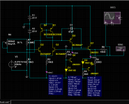
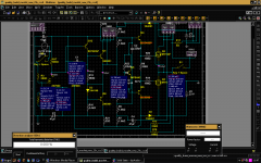
i tested in tina with 2n7000.
the dc offset is 125mv unlike bjt versioned -> -5.4V.
2N7000.TSM.asc must be renamed to 2N7000.TSM
&
2n7000_amp.TSC.asc -> 2n7000_amp.TSC respectively.
more distortion with 2N7000 unlike BC546, but better offset.
the dc offset is 125mv unlike bjt versioned -> -5.4V.
2N7000.TSM.asc must be renamed to 2N7000.TSM
&
2n7000_amp.TSC.asc -> 2n7000_amp.TSC respectively.
more distortion with 2N7000 unlike BC546, but better offset.
Attachments
Last edited:
- Status
- This old topic is closed. If you want to reopen this topic, contact a moderator using the "Report Post" button.