N-channel experts advice needed.
A long time repair issue:
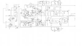
This N-channel amp has a bad habit of occasionally taking out the lower FET (Q102) on power up.
I am reasonally experienced with both complementary and sziklai output stages, but not so much with FET quasi, and this one annoys me a bit")
It can run beatifully for weeks, and then at turn on - boom, lower FET shorts.
What could cause this seen from a schematic point of view?
Could it be a result of uneven supply start-up voltage timing?
I am especially thinking of the positive 15V driver pull-up supply (Q14)...if this starts up quicker than the main supply, could this then keep the gates of the FETs fully open when the main supply kicks in?
Are there any potential oscillation issues not covered in the schematic that could cause it?
Can you think of any special reason that it is always ( three times) the lower FET that goes?
Background info:
The amplifier is a Sirius DMX100...a predecesser of the old Gamut series...probably not comparable with the newer Gamut stuff since ownership and constructor are different.
The schematic is reverse engineered, originally not by me but I can verify that the gainstage and output stage is acurate, and I have added the component values.
The original FETs are unknown since they were debadged by the constructor, so I am using IRFP240 with 100 ohm gatestoppers (was 27ohms with the unknown original FETs) and 15V zeners between gate and source.
Power supply is +-60 volt with 10.000uF per half.
Some other repairs have been done by me, including a new bias-pot.
As before said: It runs fine for weeks, maybe months, so I am kind of sure that the cause is not down to a faulty repair.
Any hints will be much appreciated.
Tell me if you need specific info.
Regards Henrik
A long time repair issue:
This N-channel amp has a bad habit of occasionally taking out the lower FET (Q102) on power up.
I am reasonally experienced with both complementary and sziklai output stages, but not so much with FET quasi, and this one annoys me a bit
It can run beatifully for weeks, and then at turn on - boom, lower FET shorts.
What could cause this seen from a schematic point of view?
Could it be a result of uneven supply start-up voltage timing?
I am especially thinking of the positive 15V driver pull-up supply (Q14)...if this starts up quicker than the main supply, could this then keep the gates of the FETs fully open when the main supply kicks in?
Are there any potential oscillation issues not covered in the schematic that could cause it?
Can you think of any special reason that it is always ( three times) the lower FET that goes?
Background info:
The amplifier is a Sirius DMX100...a predecesser of the old Gamut series...probably not comparable with the newer Gamut stuff since ownership and constructor are different.
The schematic is reverse engineered, originally not by me but I can verify that the gainstage and output stage is acurate, and I have added the component values.
The original FETs are unknown since they were debadged by the constructor, so I am using IRFP240 with 100 ohm gatestoppers (was 27ohms with the unknown original FETs) and 15V zeners between gate and source.
Power supply is +-60 volt with 10.000uF per half.
Some other repairs have been done by me, including a new bias-pot.
As before said: It runs fine for weeks, maybe months, so I am kind of sure that the cause is not down to a faulty repair.
Any hints will be much appreciated.
Tell me if you need specific info.
Regards Henrik
Attachments
No magic answers I'm afraid, only questions.
Does the FET fail at the instant of switch on or some seconds later ? The only current paths are via the speaker (if connected by the relay), via the top FET, or via a faulty insulation washer. If via the speaker then you would surely know about that.
Have you checked the FET after removing it from the amp to make sure it is still faulty... odd question but if the insulating kit were at fault.... well you get the idea.
Assuming the speaker isn't the current path, and assuming the insulation is OK then that leaves a failure of the bias circuit.
A DC offset caused by a fault would not damage the output stage as long as the speaker were isolated.
A bias issue could cause a destructive current to flow. Why the lower one fails I don't know.
Could the FET type be a problem ? Have you compared Vgs of the two channels output devices to see if they are comparable. That could be a clue as to the type of device fitted.
The symbol is odd... could they be IGBT's ?
Edit... and could the amp be breaking into some destructive oscillation at power on. Those diodes look a bit unlikely on the gate. After some thought, methinks this is down to the devices used at this point.
I think it's gate stoppers. Change to 220R on each IRF, and then add a 100pF-100R snubber between each gate and drain.
All fets require a bit of infrastructure to remain alive. I would suggest much bigger FQA mosfets here rather than the IRFPs, assuming you are using a single pair with 60V rails.
Hugh
All fets require a bit of infrastructure to remain alive. I would suggest much bigger FQA mosfets here rather than the IRFPs, assuming you are using a single pair with 60V rails.
Hugh
Still appreciated... I am not expecting a full disclosure... just may be a few hints of what could be the reason, so that I can modify with some preventive measures.No magic answers I'm afraid, only questions.
Does the FET fail at the instant of switch on or some seconds later ? The only current paths are via the speaker (if connected by the relay), via the top FET, or via a faulty insulation washer. If via the speaker then you would surely know about that.
Have you checked the FET after removing it from the amp to make sure it is still faulty... odd question but if the insulating kit were at fault.... well you get the idea.
It blows instantly so the delayed relay keeps the faulty reason to be within the circuit itself. Yes I have checked: The FET is definitely dead after removal also.
Assuming the speaker isn't the current path, and assuming the insulation is OK then that leaves a failure of the bias circuit.
A DC offset caused by a fault would not damage the output stage as long as the speaker were isolated.
A bias issue could cause a destructive current to flow. Why the lower one fails I don't know.
Yes you are right, the bias circuit is also my own primary suspicion.
I guess I am just grasping after some other possible small overlooked details construction-wize. Something that maybe is a total self-given fact with experienced N-channel quasi experts, but could be missing here !?!
I have followed your thread on your own amplifier - I regard your views highly valuable.
Could the FET type be a problem ? Have you compared Vgs of the two channels output devices to see if they are comparable. That could be a clue as to the type of device fitted.
The symbol is odd... could they be IGBT's ?
The Sirius amplifiers was quite spoken of in the Danish high-end society back in the days, and I have read all relevant info and an interview of Ole Lund-Christensen (original Sirius/Gamut owner but not the constructor) and from this I know that it is definitely some "industrial MOSFETs" ...not IGBTs and not lateral/audio MOSFETs.
So never mind the symbol ... some fellow just used this when he reegineered it, it doesn't mean anything. I got the schematic from this thread on DIYaudio, and I have skeptically checked the sections already mentioned and it is the same.
I have not checked the Vds or matched the FETs before usage, as I reckon this should not matter too much, since the bias circuit (!) and the DC-servo should make everthing wonderfully autobalancing.
I do trim the idle checking the voltage over the source-resistors the times I have replaced the defective device. The difference between the voltagedrop over the upper and lower source-resistor is less than 10%, but I have not given this more thoughts. I think it could be down to teh nature of the quasi-complementary topology, differences in the voltmeters or maybe a variations in the actual value of the resistors.
Anyway: again since the amplifier is working great between the faults and since the rest of the circuit seems to be in balance, I have a hard time thinking this could be the reason.
But please let me know if you disagreee.
Edit... and could the amp be breaking into some destructive oscillation at power on. Those diodes look a bit unlikely on the gate. After some thought, methinks this is down to the devices used at this point.
The oscillation part is exactly what I am curious about. The issue is that is is hard to measure it since the fault is very much periodically, and there is no other suspicious behavior to keep one from using it daily.
Your view on the diode-ting sounds like something I should know more about.
I know that the Vertical MOSFETs are faster and more oscillation-prone than the Lateral Audio MOSFETs. Since this amplifier apparently uses vertical types I would like to stick to this and just cure the oscillation issue.
I guess the diodes are there for making the gate discharge happen quicker than the charging, so that would actually decrease the risk of a gate being unintentionally open.
What would your concerns be? ( speaking conceptually is fine)
Thank you for the feedback Mooly
I think it's gate stoppers. Change to 220R on each IRF, and then add a 100pF-100R snubber between each gate and drain.
All fets require a bit of infrastructure to remain alive. I would suggest much bigger FQA mosfets here rather than the IRFPs, assuming you are using a single pair with 60V rails.
Hugh
Yes, that might be necessary.
I thought increasing the gatestopper to 100 ohms instead of 27 ohms already had me covered, but better be extra safe.
I will look into the the FQA MOSFETs.
Thanks Hugh
Last edited:
Well each gate seems to driven from its own 'push pull' driver which is unusual. I see an 8.2 volt zener on the input to each driver which is a means of limiting the Vgs potential.
The diode is not conventional. We might use something like that on a bjt device used a switching transistor (such as an SMPS) but not an audio amp using FET's. The junction capacitance of the diode is ever present as well which is like shunting the gate stopper with a cap... just what we don't want.
I still think the original outputs might not be quite what you think they are. 8.2 volts as a Vgs limit isn't much for a vertical FET like the IRF240. They are good for around -/+20 volts typically.
Hughs suggestion is worth looking at. I would remove those diodes and increase the stoppers a little. That would usually be enough. Snubbers are forcing the issue (you will not oscillate) but maybe they are needed here.
I would compare the Vgs of the original channel FETs. Just measure it with it biased correctly and compare. Do it at the driver end of the gate stopper though. The meter leads could provoke oscillation.
The diode is not conventional. We might use something like that on a bjt device used a switching transistor (such as an SMPS) but not an audio amp using FET's. The junction capacitance of the diode is ever present as well which is like shunting the gate stopper with a cap... just what we don't want.
I still think the original outputs might not be quite what you think they are. 8.2 volts as a Vgs limit isn't much for a vertical FET like the IRF240. They are good for around -/+20 volts typically.
Hughs suggestion is worth looking at. I would remove those diodes and increase the stoppers a little. That would usually be enough. Snubbers are forcing the issue (you will not oscillate
) but maybe they are needed here.I would compare the Vgs of the original channel FETs. Just measure it with it biased correctly and compare. Do it at the driver end of the gate stopper though. The meter leads could provoke oscillation.
I still think the original outputs might not be quite what you think they are. 8.2 volts as a Vgs limit isn't much for a vertical FET like the IRF240. They are good for around -/+20 volts typically.
I would compare the Vgs of the original channel FETs. Just measure it with it biased correctly and compare. Do it at the driver end of the gate stopper though. The meter leads could provoke oscillation.
The FETs in the healthy channel (with the originals) measures around 3.02 volt and 3.28 Volt at the driver side of the gatestopper, at approximately 170mA idle-current
I would think that the 8.2 V zeners are probably just a sort of crude overcurrent safety measure. Since we don't know what the original ones were, it is hard to guess what kind of output current that would allow for.
Thanks again for your views...Hugh's suggestion on increased gate-stopper measures are definitely on the to-do list.
Edit: And I will also be removing the diodes across the gatestopper.
Last edited:
3 volts sounds a little bit on the low side for IRF240 types. You would need to compare channels to prove it though. I was also thinking of the 2SJ200 types but I think they would come in at a lower Vgs than 3 volts. You would think there would be some info out there on what they used.
You might well crack it by changing the stoppers though.
You might well crack it by changing the stoppers though.
The push pull drivers on the gates are an innovative approach I first saw from Kanwar, a very clever young Indian designer who builds and sells very powerful mosfet amps into the very large Indian market. He swears by it...... but then he is using very, very large output stages with many nF of Ciss to contend with.
In a domestic amp I do not regard them as essential because the high gate capacitance is no more than 1nF and is bootstrapped by the source follower configuration anyway.
I would not suggest removing it however because we are trying first to find the fault.
I have seen small hexfets self-oscillate with only 100R gate stoppers in Class AB situations. We know Class AB is more critical, since the mosfets switch, provoking this oscillation issue. I notice NP always recommends 220R stoppers on all his designs with IRFPs; this is a good place to start!
. I notice NP always recommends 220R stoppers on all his designs with IRFPs; this is a good place to start!
I always use 390R and never had any problems.
- Status
- This old topic is closed. If you want to reopen this topic, contact a moderator using the "Report Post" button.
- Home
- Amplifiers
- Solid State
- N-ch quasi - blows lower FET