Nakamichi IA-2 CAPS
Hi, Ian.
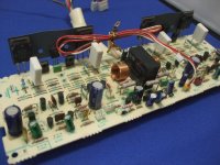
Many thanks for your new reply. I pulled a Nichicon 2,2OOμF 16v from the Power Supply PCB and it measured just below half of rated value. So, it looks like I have a lot of work to do...
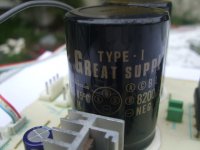
My biggest problem may be sourcing the three-leg caps in attached photo.
They are marked NICHICON, TYPE-1, GREAT SUPPLY, A C BLANK, B 8,200μF 50WV, NEG BLACK. The seem to be specials. I queried Nichicon but got no reply. And I can't find anything like them on the Internet.
Hi, Ian.
Many thanks for your new reply. I pulled a Nichicon 2,2OOμF 16v from the Power Supply PCB and it measured just below half of rated value. So, it looks like I have a lot of work to do...
My biggest problem may be sourcing the three-leg caps in attached photo.
They are marked NICHICON, TYPE-1, GREAT SUPPLY, A C BLANK, B 8,200μF 50WV, NEG BLACK. The seem to be specials. I queried Nichicon but got no reply. And I can't find anything like them on the Internet.
Attachments
I understand this since I have had to scrap many old amplifiers that could not be repaired to original condition because of special, irreplaceable caps. In cases where owners are reasonable, it is not difficult to fit modern, smaller capacitors on a small PCB mounted above the main PCB. This is not straightforward repair work and one may need to innovate or enlist the help of others to do this......My biggest problem may be sourcing the three-leg caps in attached photo......
Because appearance is important some folk, I have seen replacement caps fitted inside some huge old capacitor cases. I even have special audio caps from large JVC and Denon amplifiers from the 1970s with 3 smaller caps inside, as original components!

However, it may not be necessary to replace these large caps yet. Smaller caps can often fail sooner and give the impression that everything is failing at once - probably not true and we could just be replacing everything as a precaution rather than necessity. The proper way to test the main power supply electrolytics is to observe the mains ripple on the DC output of the power supplies with an oscilloscope. This requires the power supply to be loaded with a suitable dummy load(s) that approximates the amplifier load at full rated power output.
You can be certain that original spare parts will have deteriorated too, so whatever you fit, should be of recent manufacture. That's a sad fact of electrolytic capacitors, even the very best quality and highest price imaginable.
Hi, Ian.I understand this since I have had to scrap many old amplifiers that could not be repaired to original condition because of special, irreplaceable caps. In cases where owners are reasonable, it is not difficult to fit modern, smaller capacitors on a small PCB mounted above the main PCB. This is not straightforward repair work and one may need to innovate or enlist the help of others to do this.
Because appearance is important some folk, I have seen replacement caps fitted inside some huge old capacitor cases. I even have special audio caps from large JVC and Denon amplifiers from the 1970s with 3 smaller caps inside, as original components!
However, it may not be necessary to replace these large caps yet. Smaller caps can often fail sooner and give the impression that everything is failing at once - probably not true and we could just be replacing everything as a precaution rather than necessity. The proper way to test the main power supply electrolytics is to observe the mains ripple on the DC output of the power supplies with an oscilloscope. This requires the power supply to be loaded with a suitable dummy load(s) that approximates the amplifier load at full rated power output.
You can be certain that original spare parts will have deteriorated too, so whatever you fit, should be of recent manufacture. That's a sad fact of electrolytic capacitors, even the very best quality and highest price imaginable.
Many thanks again for your support. I think I will leave these two caps for the time being. (Perhaps the three terminal Vishay on page 3 of attachment could be used.)
Attachments
Proper Service Manual for Nakamichi IA-2
Greetings,
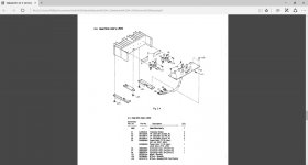
I need a proper service manual for the Nakamichi IA-2 Amplifier. (The service manual I have is just exploded views and parts lists.)
I need to know how to remove:
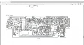
1. 05 Power Amp PCB Assy (P 7)
2. 3.3 Front PCB Assy (P 8)
Many thanks if you can help.
Greetings,
I need a proper service manual for the Nakamichi IA-2 Amplifier. (The service manual I have is just exploded views and parts lists.)
I need to know how to remove:
1. 05 Power Amp PCB Assy (P 7)
2. 3.3 Front PCB Assy (P 8)
Many thanks if you can help.
Attachments
Proper Service Manual for Nakamichi IA-2
I probably needed a service technician's manual, so thanks for your good advice.
Have already removed the heat sink assembly after struggling with some of the connectors.
Cheers!
Um.
That is the "proper" service manual.
I have multiple Nak manuals, and thats all you will get.
Sounds like what your after is a screw by screw disassembly manual.
It doesn't exist.
Use common sense and it will come apart and go back together just fine.
I probably needed a service technician's manual, so thanks for your good advice.
Have already removed the heat sink assembly after struggling with some of the connectors.
Cheers!
Nakamichi IA-2 CAPS
Greetings everyone.
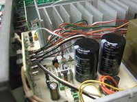
I recently started and finished the Power Supply PCB.
For the Power Amp PCB and Front PCB (Tone and volume controls and selectors), I was planning to mainly use Panasonic FC caps to replace the Nichion VX caps but I can't find some values.
Power Amp PCB:
1. Nichicon Muse (Green), 10mfd/50VDC and 47mfd/16VDC ===> ?
2. Nichicon VP(BP), 100mfd/16VDC ===> ?
3. Nichicon VX(M), 10mfd/63VDC ===> ?
Front PCB:
1. Nichicon VX(M), 0.1mfd/5.5VDC, 0.47mfd/50VDC and 1mfd/5VDC ===> ?
Many thanks for your time and recommendations.
Greetings everyone.
I recently started and finished the Power Supply PCB.
For the Power Amp PCB and Front PCB (Tone and volume controls and selectors), I was planning to mainly use Panasonic FC caps to replace the Nichion VX caps but I can't find some values.
Power Amp PCB:
1. Nichicon Muse (Green), 10mfd/50VDC and 47mfd/16VDC ===> ?
2. Nichicon VP(BP), 100mfd/16VDC ===> ?
3. Nichicon VX(M), 10mfd/63VDC ===> ?
Front PCB:
1. Nichicon VX(M), 0.1mfd/5.5VDC, 0.47mfd/50VDC and 1mfd/5VDC ===> ?
Many thanks for your time and recommendations.
Attachments
- Status
- This old topic is closed. If you want to reopen this topic, contact a moderator using the "Report Post" button.
- Home
- Amplifiers
- Solid State
- Recommendations re Nakamichi IA-2 maintenance