Just received the Audio Advisor catalog SP116 and noticed this blurb on page 5, about the Bryston 4B cubed power amp
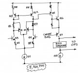
It shows an input stage with a two complementary feedback pairs in a differential amplifier, with a current mirror load, and a third CFP used as a second stage, plus cascode. I redrew it below because the figures in the patent are crapped up with shaded overlays.
For this they got a patent?
_
The new 4B3 power amplifier -- and all of Bryston's Cubed Series amplifiers -- features a new patented input circuit developed in conjunction with Dr. Alexandru Salomie that is precisely optimized and linear beyond any that Bryston has used before. ... The new input stage is so transparent its measurable distortion is less than 1/1000th of 1 percent!
So I visited the US Patent and Trademark Office website and searched for patents that either (a) had Alaxandru Salomie as one of the named inventors; or else (b) was assigned to Bryston. I only found one: US Patent number 8,466,744 (attached below).
It shows an input stage with a two complementary feedback pairs in a differential amplifier, with a current mirror load, and a third CFP used as a second stage, plus cascode. I redrew it below because the figures in the patent are crapped up with shaded overlays.
For this they got a patent?
_
Attachments
I've seen worse.For this they got a patent?
The patent is worth skimming. But if one wanted to do something similar, their level of detail makes it easy to make a few changes and be unencumbered. Not that I would want to copy it anyway...Maybe what they're patenting is how many transistors they used to achieve this result?
The question is whether it is true that it has the lowest distortion. How complicated is irrelevant, it's the result that matters. Just because it's simple does not mitigate the value of the idea. If it is that simple, how come he's the first one that did this. If someone actually designed and well documented about it, they can challenge the patent and get some money out of it.
If it really works, hats off to him.
I am not defending Bryston, in fact, I just bought a Nakamichi PA-7 designed by Nelson Pass. I was shopping around including Bryston and Krell. I don't care too much of Bryston reading the schematic so I decided to narrow to Threshold and Krell......but no S/300 available after waiting for 2 months, so I get the Nakamichi instead.
Last edited:
The patent is worth skimming. But if one wanted to do something similar, their level of detail makes it easy to make a few changes and be unencumbered. Not that I would want to copy it anyway...
The benefit/tradeoffs of that input stage taken in isolation are easily quantified. There are a lot more claims beyond this in the patent possibly making it so narrow that one wonders why they bothered.
BTW Fairchild disclosed a CFP input stage for an instrumentation amplifier in 1974.
Last edited:
The oddest part for me at first glance: why on earth does he return the input PNP collectors to the current source? Real CFPs will have the collector go to the emitter of the input device.
I threw this into sim with 100 ohm emitter Rs and 1k base-emitter R in the PNPs. 5mA tail current. I loaded the output of the mirror etc. with 10k to 25V and used a 30V positive rail. 0.392% with 10kHz to 9th harmonic.
With the more conventional CFP connection this drops to 379ppm, after adjusting the input drives to produce the same output voltages.
Fine scale stability issues? All I know this has prior art back to at least 1968The oddest part for me at first glance: why on earth does he return the input PNP collectors to the current source?
(Barry Blesser's "super" transistor).
Anyone actually read the patent? there must be some tricks how he adjust the tail current, R6 and R7 for optimal value. I don't think you can just put in values and get the result.
Again, I am not at all defending the guy. I am just more curious than anything else and I am too lazy to do the work .
.
Again, I am not at all defending the guy. I am just more curious than anything else and I am too lazy to do the work
.I don't see any hint of peaking or other anomalies in either the patent case or the more conventional (and indeed very old) differential CFP case.Fine scale stability issues? All I know this has prior art back to at least 1968
(Barry Blesser's "super" transistor).
The second stage is also odd with a similar departure from CFP. Maybe there is some sort of complementarity when the second stage is considered, although that sort of thing is only likely to be manipulable to reduce even order.
Puzzling and still pretty much anything but news. I guess we have to be reminded periodically of the broken patent system.
I skimmed through it, particularly the figures. As I remarked the approach to phase compensation is of some interest, although I suspect not really novel.Anyone actually read the patent?
The transimpedance nonlinearity of the input stage is insignificant compared to the harmonics it absorbs from the VAS, because it only drives a few uA or so of current. Having the CFP collectors on the other side of the degeneration increases LTP gain (in theory) and thus total feedback.
BTW, the schematics in the patent are in fact LTspice simulations, complete with flawed simulator models, so the stability compensation values in the schematics are likely a far away dream. It's not stable when good models are used.
BTW, the schematics in the patent are in fact LTspice simulations, complete with flawed simulator models, so the stability compensation values in the schematics are likely a far away dream. It's not stable when good models are used.
Last edited:
Yes, agree that the input stage nonlinearity in an overall amplifier is a relatively small effect. It would be mildly interesting to know what they told the AA blurbista.The transimpedance nonlinearity of the input stage is insignificant compared to the harmonics it absorbs from the VAS, because it only drives a few uA or so of current.
- Status
- This old topic is closed. If you want to reopen this topic, contact a moderator using the "Report Post" button.
- Home
- Amplifiers
- Solid State
- New Bryston input stage measurable distortion < 0.001% (Audio Advisor)