Without the if I disconnect the earth from the power cord the hum is actually really bad. I would love to keep the original Class II protection but than I will have to find another way to get rid of this nasty hum. Whenever I approach my finger to the signal wires coming in to the preamp it gets 10 times worse.
I will try some different values for the filter resistors to see if that makes any difference.
I don't have any resistor over 100k right now so I will have to get some anyway, might as well get 100 and 120k ones.
When tone defeat is on, hum is a little better but hiss doesn't change really.
I will try some different values for the filter resistors to see if that makes any difference.
I don't have any resistor over 100k right now so I will have to get some anyway, might as well get 100 and 120k ones.
When tone defeat is on, hum is a little better but hiss doesn't change really.
When did this hum come in again? Was it with the extra power ground? (Have you tried attaching that to F-2598 yet?) Or was it with the regulator mods?Without the if I disconnect the earth from the power cord the hum is actually really bad. I would love to keep the original Class II protection but than I will have to find another way to get rid of this nasty hum. Whenever I approach my finger to the signal wires coming in to the preamp it gets 10 times worse.
You've got to consider that circuitry on F-2602 and F-2603 is fairly high impedance, and at the preamp input it's highish impedance with partly very low signal levels. That spot is very sensitive, and there should really be some coax or other shielded cable connecting F-2603 and F-2604, but since you write "wires" I suspect that isn't the case.
What you could try is taking a fourth piece of wire (not too thin), loosely winding it (in helix shape) around the three ones connecting F-2603 to the preamp input, and connecting it to post 46 (ground) at both ends. That's arguably not the greatest shield in the known universe but should get the job done.
The ground connections from F-2603 to F-2602 and back to F-2598 could probably also do with some reinforcement. Board traces look reasonably beefy as-is except for the middle area on F-2604 itself. I would also change grounding on F-2602/03 a bit - cut the 41-41 connection, instead run a wire from 46 to 38 (or close) along the existing ground traces. Ideally, that's 46 over on F-2604. I bet doing so would already have cut down on induced noise significantly, you might not even have needed the extra power ground then. (It would have diverted the noise current around all of F-2602 and F-2603.) The 46-46 connection should be fairly stout to avoid degrading channel separation at low volumes, but that should already be sorted with the extra shielding effort. Ideally I'd want to implement a full star ground but that gets tricky with those shielded connections, I'd have to think about that some more.
BTW, it would be interesting what the ohmmeter has to say on the connection from F-2604 to the ground screw stock.
I would also consider making a shield for F-2603 (and maybe F-2602 as well) that can be mounted maybe 0.5..1 cm away from the PCB's back side. It doesn't have to be a solid metal plate, a grid of bare wire pieces (a popular soldering exercise) would also do while being more easily supported mechanically.
Another test I'd do with the multimeter:
On AC range, measure voltage from circuit ground to earth.
Turn around power plug and repeat.
What sort of values do you get?
Hmm. How much is hiss still increasing when you turn up the volume?When tone defeat is on, hum is a little better but hiss doesn't change really.
Okay so I did what you said and cut the 41 to 41 ground connection and got a wire straight from 46 to 38, than I added a ground wire around the left and right channel signal input from F-2603 to F-2604 and connected the ground for the preamp filtering directly to the chassis on F-2598.
The hiss is now way way down and doesn't really change with volume except when tone defeat is OFF (because I didn't add any filtering there yet). No hum when volume is down but it gets fairly loud when I turn it up and is still very sensitive to me touching the chassis or even approaching the preamp boards F-2602 ~ F-2604. I will see later on if I can get that shielding done.
I have got 129v ac from chassis to earth one way and 52v ac the other way...
Phew. Theory and practice are aligning for once. Can't beat a decent star ground and some extra PSRR.Okay so I did what you said and cut the 41 to 41 ground connection and got a wire straight from 46 to 38, than I added a ground wire around the left and right channel signal input from F-2603 to F-2604 and connected the ground for the preamp filtering directly to the chassis on F-2598.
The hiss is now way way down and doesn't really change with volume except when tone defeat is OFF (because I didn't add any filtering there yet).
You get hum when touching the chassis? That's weird. The chassis should be firmly connected to circuit ground via F-2598 (which then goes to F-2602 post 38), acting as a Faraday cage with the case closed (assuming the lid is making good contact). In no way should it be able to couple stray signals into the circuit.No hum when volume is down but it gets fairly loud when I turn it up and is still very sensitive to me touching the chassis or even approaching the preamp boards F-2602 ~ F-2604. I will see later on if I can get that shielding done.
Stupid question - you don't happen to be testing with the input open? Could you make something to temporarily short out both channels of a high-level input? (A low-impedance source would also work.) We are, after all, talking about 250 kOhms of input impedance, with non-ideal shielding that's one rather nice antenna potentially extending from the volume pot back over the tone controls, input selector and input board. Let's try that again with the lid back on and input shorted in order to avoid chasing ghosts.
Now you should determine where phase is in the outlet that you used and mark the plug so you get the lower value (52 V) in use.I have got 129v ac from chassis to earth one way and 52v ac the other way...
Do you know the input impedance of your multimeter? That would allow estimating how much mains coupling there is. We are talking pF range when shielding works well. With 10 Megohms of multimeter Zin, we'd have something like 180 pF to phase in one direction and 75 pF in the other. Decent enough for a transformer of a certain size, I suppose, though not exactly earth-shattering (if still more than an order of magnitude better than a lot of SMPS-equipped gear, which tends to be ~1 nF range). A certain asymmetry in values is expected because the primary winding does not couple to the secondaries equally everywhere, so mains coupling varies according to which end is phase and which is neutral.
Just in case, I would check for continuity between the transformer's shield winding (that's the black wire) and the center taps (white / grey) and F-2598 ground. If that's fine, coupling is as low as it's going to get with this transformer.
Hmm, according to the picture here, the power supply star ground (where the aforementioned wires are joining) is on a somewhat wimpy-looking wire "bar" right between the big smoothing capacitors. It is generally preferred to T the capacitor junction off a bit, but if you don't have a buzzing problem right now, better leave this as-is. You can do the math on how much this piece of steel(?) wire is going to add to capacitor ESR. It's not something one would do like that today.
Just a quick answer to say that I feel quite stupid, I got used to just putting the lid back without screwing it tight to close the amp for testing. Now I noticed there was a little piece of foam between the lid and the the actual cage of the amp where the 4 screws go (this does seem non factory and I don't really see why someone would put it there). I pulled it off, put the lid back and now it makes good contact so bye bye hum.
I won't develop my answer on the rest of your although very interesting message. I will install the filtering for the tone control circuit tonight or tomorrow and will let you now if that gets rid of the tiny tiny bit of hiss that still remains (with speaker I reaaly have to stick my ear to them in order to hear it but with headphones it's there if there is no other background noise in the room). It is very acceptable but could be better still.
I won't develop my answer on the rest of your although very interesting message. I will install the filtering for the tone control circuit tonight or tomorrow and will let you now if that gets rid of the tiny tiny bit of hiss that still remains (with speaker I reaaly have to stick my ear to them in order to hear it but with headphones it's there if there is no other background noise in the room). It is very acceptable but could be better still.
Sounds like noise over the speakers is OK now, so you may want to tackle the headphone output like I suggested earlier. That would not only reduce the excessive gain (about 35 dB with a 100 ohm load, where a dedicated headphone amp might have 14-20 dB), but get output impedance a bit closer to hi-fi territory as well.
What kind of headphones are you using?
What kind of headphones are you using?
Oh I didn't see that part about the headphone output, did you add it after posting the original message ? Just did that together with the filtering for the tone control bias circuit and it is perfect now, or at least perfect in comparison to what it was before. No more hiss even with the volume all the way up, and at that point there is some very faint hum but I will damage something else before getting there.
I use some Sennheiser Momentums, I think they were designed for use with ipods and stuff...
Anyway some amazing help and advice I got from you, thank you !!
I just need to get some heat sink compound on the power transistors, check the bias one last time and give the outside a good clean and then I will post some pictures.
Quite possibly so, as I often do that.Oh I didn't see that part about the headphone output, did you add it after posting the original message ?
That sounds good. Stock hiss levels must have been insane.Just did that together with the filtering for the tone control bias circuit and it is perfect now, or at least perfect in comparison to what it was before. No more hiss even with the volume all the way up, and at that point there is some very faint hum but I will damage something else before getting there.
OK... ~22 ohms at 1 kHz, taking about 22 mV for 90 dB SPL (quite sensitive). Effective overall gain with these, stock, ~25 dB.I use some Sennheiser Momentums, I think they were designed for use with ipods and stuff...
What value resistor did you end up using? 100R wouldn't do an awful lot with these yet.
Momentums are basically OK (and quite unaffected by output impedance) but a bit short on highs. Sennheiser have rarely been the go-to company when it comes to closed headphones (HD25 excepted, and HD280 is an OK workhorse, but most of their stuff tends to be less than breathtaking). Maybe look for some classic HD580/600s or 650s (but do research earpad prices...). 500 series ones also tend to be quite good but can be rather finicky with output impedance since their impedance response is rather variable... I'd give an HD598 less than 10 ohms of possible, that's getting a bit tricky with them resistor dividers.
OK, but be careful not to blow anything up at this stage. Would be a shame after all the work you put into this one.I just need to get some heat sink compound on the power transistors, check the bias one last time and give the outside a good clean and then I will post some pictures.
I might turn this little episode into a brief writeup in my blogalike. It's definitely given me some ideas. I always thought hiss level in my trusty late-'90s Onkyo surround receiver (which is not that much and definitely better than some but still audible from 1 m away with 88 dB/2.83 V speakers) would be limited by its NJM4558, which ought to be in the same ballpark as your Sansui's preamp section noise wise. But what if there is power supply being fed into audio ground via the decoupling caps on a "ground is ground" basis? It sure looks like that in the schematic, the power and audio ground return from the preamp PCB to main PCB appears shared. Eww. It would never have occurred to me that this could be an issue, and lower-noise regulators may hence be beneficial. Lessons learned - high PSRR is basically great but easily degraded by subpar layout.

Years ago I came across an extensive mod of a high-end Yamaha FM tuner (T-85, or T-80 maybe?). With new electrolytics and a nice star ground using beefy wires under the PCB, the unit became a good bit quieter. I think now I know why that is...
Last edited:
I find there to be a little too much bass with these headphones on most amps, they sound good when used directly on a cd player, computer or ipod which is what I use them for most of the time. I usually only listen to my amps through my speakers so I don't think I will spend any money in new headphones any time soon but thanks for the advice.
I went with some 35R 2W resistors because that was the closest I had right now, It was clearly enough to get the hiss down and I don't want to modify it too heavily because as I said I won't use it as a headphone amp very much (only when testing actually) but somebody else might later on.
I'm used to getting the sticky stuff on those transistors and always check three or four times nothing is shorted before turning on the amp again so all went well there. I did a little test and got up to 53W into 8R before clipping so that's very decent for a 45W amp, I will have to get myself a distortion analyser someday.
Happy to hear this whole thing wasn't only beneficial for me but for you as well, I guess one never stops learning. I will most definitely keep this in mind for next projects to come.
The weather here was quite bad so there wasn't much light to take any pictures but the forecast for tomorrow is better.
That's about 4 dB less level than before. In terms of noise that's only just audible this can make a big difference.I went with some 35R 2W resistors because that was the closest I had right now, It was clearly enough to get the hiss down and I don't want to modify it too heavily because as I said I won't use it as a headphone amp very much (only when testing actually) but somebody else might later on.
Maximum no-load output voltage remains at a decent ~2.8 Vrms, I don't see a problem driving most headphones like that (most headphones that aren't a HiFiMan HE-6, that is).
Back in those days, specifications would usually be quite generous still. Not any more so 5-10 years later. Same goes for 10000 µF capacitors on a 50 Wpc amp, even if they partly have to make up for lowish supplies here.I did a little test and got up to 53W into 8R before clipping so that's very decent for a 45W amp, I will have to get myself a distortion analyser someday.
You don't really need a distortion analyzer these days (not for simple amps like this, though BTL is a different story), as long as you have a decent soundcard, a passive attenuator of about 30 dB (maybe 22k / 680R, times 2), and can find a good way of eliminating the ground loop inherent in a loopback setup - some people have included 1k resistors in the ground between attenuator and audio cable going to line-in. Even relatively basic onboard audio should be good for up to 192 kHz of sample rate and distortion down in the -80dBc vicinity @1 kHz, the bottleneck generally being the ADC side of things. That's about as good as a classic distortion analyzer with components that you should already have or be able to make quite easily (a few resistors, wires and an output jack on a piece of perfboard for the attenuator sounds easy enough).
It was quite stormy around here, too.The weather here was quite bad so there wasn't much light to take any pictures but the forecast for tomorrow is better.
I know I could get away with using the sound card from my computer with just some adapting but still I like having the piece of equipment on my bench, next to my oscilloscope and a function generator that needs some attention. I've only been doing this for a couple of years so I'm slowly starting to invest in this stuff. Maybe for now though I might just go with the little adaptor to be able to use my computer.
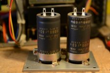
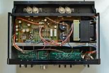
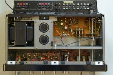
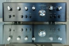
Here are some pics as promised :


Here are some pics as promised :


- Status
- This old topic is closed. If you want to reopen this topic, contact a moderator using the "Report Post" button.
- Home
- Amplifiers
- Solid State
- Sansui AU 5900 dead channel