Depaj
A798 and brothers or cousins might work well outside the circuit and produce all shorts of problems under voltage or operating temperature .
Ceramics and resistor hardly ever produce this type of failure except the ones we already talked about .
Please check a number of screws that support the boards make sure that these are clean and tight .
Remember that this style of amplifier doesn't actually use a star ground system even though it looks like it does ...many of the circuits are grounded from the enclosure locally and all around ..Check that
katieandad
This is bad practice and time consuming procedure that might cause complications ...Electro's are to be removed one way or another with no questions asked ..>Even if you find one that is broken and you replace it who is the one to guarantee that the next one will be broken after 1-6 month of everyday operation ...Think though that we have met before in this issue and its nice to know that you care about this
Hi east electronics
I have had trouble with 2SA979 Dual transistors before, they also tested fine but in circuit they were no good. I will have to order These 2SA798 as they are not available in an every day electronics shop. I also replaced the 4 220R resistors, all the small signal 2sc1313 and 2sa726 transistors in the preamp which calmed the hiss a little but not entirely, and will replace all the electrolytic caps soon. The dc in my first test was due to he fact that the grounding of some parts of the power amp section are connected with the plugs coming from the preamp and I took my reading with that plug disconnected. Now everything works fine except from the pretty loud hiss, independent of volume but definitely coming from the preamp (as the power amp is dead silent when disconnected) and a buzz appearing when volume is half way.
I have had trouble with 2SA979 Dual transistors before, they also tested fine but in circuit they were no good. I will have to order These 2SA798 as they are not available in an every day electronics shop. I also replaced the 4 220R resistors, all the small signal 2sc1313 and 2sa726 transistors in the preamp which calmed the hiss a little but not entirely, and will replace all the electrolytic caps soon. The dc in my first test was due to he fact that the grounding of some parts of the power amp section are connected with the plugs coming from the preamp and I took my reading with that plug disconnected. Now everything works fine except from the pretty loud hiss, independent of volume but definitely coming from the preamp (as the power amp is dead silent when disconnected) and a buzz appearing when volume is half way.
I replaced the 2 SA798 and now the amp is stable, relay closes, almost no dc offset and was able to set bias without any problem. Still I have a fairly loud hiss coming from the preamp (it's gone when I disconnect pre and power amp. I already replaced all electrolytics and those 2sc1313/2sa726 everywhere. Although usually a ground problem would more likely give a buzz I checked for grounding around the entire amp and everything seems ok.
I left the amp sitting for a while but am really eager to be able to listen to it. Everything works and the sound is good but even with the volume all the way down I have a quite audible hiss, especially with headphones. It definitely comes from the preamp because it disappears when I disconnect the preamp from the main. Also I'm able to get rid of all the hiss when turning both mid and high all the way to minimum. I replaced all electrolytics and small signal transistors, replaced the zener diode and the two regulator transistors in the secondary power supply but nothing changes anything. Is this amp just not quiet at all or am I missing something here ?
That's normal. All old (early to mid 70s) Sansui preamps hiss quite loudly, even when restored. This includes the top of the line models. You can't fix it. Most people don't seem to mind/notice it. I guess they just have bad speakers or hearing. I just use my old Sansuis as power amps. Bypass the junky pre and connect a nice dac with a volume control in its place.
Last edited:
I did read that a lot but I have an AU-222 and an AU-3900 and both of them are very quiet in comparison to the AU-5900. The 222 has a very slight hum but almost not noticeable and the 3900 is very quiet. How come the 5900 that is from the same series as the 3900 has such a bad preamp ?
I didn't do any further testing today but from what I know from my previous tests it isn't the tone control because when I bypass it I still get the hiss, that's why I thought it could only come or from the preamp section on board F-2604 or the secondary power supply that feeds the preamp section. But than again I replaced all the electrolytics, all the small signal transistors (same in power supply plus the regulator transistors and the zener diode). Anyway it's down to those two I would say.
Back again after some tests :
-first I injected the signal directly at the input of the preamp (bypassing both F-2602 and 2603) and the hiss was still there.
-Than I took the signal from F-2603 and directly injected it into the tone control board (bypassing the preamp section) and the hiss was gone.
First I suspected the secondary power supply that feeds the preamp (because I can pick up some noise with the oscilloscope on the 22v supply. But the phono equalizer is also supplied by this circuit and that is very quiet.
So the only thing that is left is the preamp section itself but as I said, transistors are new (sa992/sc1845) and capacitors are new.
It has been a while since I last touched this amp but I'm back because I've been using it for a while on some B&W Dm4's and although it sounds really good the hiss is still there and very unpleasant.
I used the +23v from the power supply of a sansui au 2900 to feed the preamp of the au 5900 and it gets very quite and sounds perfect so it's definitely the secondary power supply that is faulty. Yet I replaced the 4 transistors, the zener diode and the resistors but the hiss is still there
I used the +23v from the power supply of a sansui au 2900 to feed the preamp of the au 5900 and it gets very quite and sounds perfect so it's definitely the secondary power supply that is faulty. Yet I replaced the 4 transistors, the zener diode and the resistors but the hiss is still there
What about the electrolytics?I used the +23v from the power supply of a sansui au 2900 to feed the preamp of the au 5900 and it gets very quite and sounds perfect so it's definitely the secondary power supply that is faulty. Yet I replaced the 4 transistors, the zener diode and the resistors but the hiss is still there
I would estimate the AU-2900 +23V supply to be a fair bit less noisy - it's only a cap multiplier that's cleaned up passively on top of that. The AU-5900 reg would have zener noise amplified by a few dB at least.
Where exactly did you inject the signal when you wrote
R19/20-ish?-Than I took the signal from F-2603 and directly injected it into the tone control board (bypassing the preamp section) and the hiss was gone.
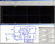
That tone amp arguably is not the last word in PSRR. Depending on transistor type, I'm seeing power supply noise on the output reduced by about 10-12 dB only when simulating the preamp. Not great. Distortion performance is OK with BC547C or 2SC4102 models, the 2N5088 fared 20 dB worse for some reason. Anyway, doing something about that would seem to be a good idea.
Ah yes, cleaning up the supply for the two 68k resistors (R03/04) with 1k + 100µ to ground in series brings this up to almost 36 dB. Still not great but kinda more like it.
It's interesting that power supply noise is the limiting factor here. I would have expected the highish-impedance surroundings (e.g. 250k volume pot) to be the culprit.
Now let's tackle the regulator... Hmm, they're running a fair bit of current through that zener, that's more than 10 mA plus almost 4 mA from the transistor. So 14-15 mA total. That won't be easy to clean up. You could cheat a bit and add some resistance in series with the zener. Like 33-100 ohms max, at which point a few hundred µF in parallel should clean things up quite nicely. Who cares about DC stability anyway. I'm also wondering whether the extra current provided by 820 ohm R43 is even needed any more then, I think they mainly did that to reduce impedance and improve regulation, since TR11 current depends on the input-output voltage differential.
If DC stability turns out to be an issue, you can always reconfigure the whole shebang for another (like 5.6 V) zener, all you have to adjust is the three gain-setting resistors R45+47-R49 and preferably give R45+R47 a little parallel cap like R59 has. Vout ~= (V(D11) + Vbe(TR11)) * (R45+R47+R49)/R49; actually it's a bit higher because of TR11 bias current. Ideally you pick a zener type such that zener and Vbe tempco just cancel at the given current.
The negative regulator just tracks the positive one in this arrangement - the R59/65 midpoint voltage must end up being Vbe(TR15) below ground.
Attachments
Last edited:
What about the electrolytics?
They have all been replaced by nichicon FG or wima mks2/Nichicon ES in signal path.
Where exactly did you inject the signal when you wrote, R19/20-ish?
It was a while ago but I think it might even have been after the tone control circuit.
That tone amp arguably is not the last word in PSRR. Depending on transistor type, I'm seeing power supply noise on the output reduced by about 10-12 dB only when simulating the preamp. Not great. Distortion performance is OK with BC547C or 2SC4102 models, the 2N5088 fared 20 dB worse for some reason. Anyway, doing something about that would seem to be a good idea.
After recommendation from some other people on the forum here I replaced all the small signal transistors by some fairchild KSA992/KSC1845, as replacing those in a previously also noisy AU-3900 did the trick.
Ah yes, cleaning up the supply for the two 68k resistors (R03/04) with 1k + 100µ to ground in series brings this up to almost 36 dB. Still not great but kinda more like it.
Just before R03/R04 there is a .022µF ceramic cap going to ground, you suggest replacing this by a 100µF +1k in series or adding this in parallel with c31/c32 ?
Now let's tackle the regulator... Hmm, they're running a fair bit of current through that zener, that's more than 10 mA plus almost 4 mA from the transistor. So 14-15 mA total. That won't be easy to clean up. You could cheat a bit and add some resistance in series with the zener. Like 33-100 ohms max, at which point a few hundred µF in parallel should clean things up quite nicely. Who cares about DC stability anyway. I'm also wondering whether the extra current provided by 820 ohm R43 is even needed any more then, I think they mainly did that to reduce impedance and improve regulation, since TR11 current depends on the input-output voltage differential.
I'm still learning a lot, how exactly is adding that resistor and cap going to clean things up ? Should I just take R43 out after installing those and see what happens or leave it be as I don't expect it can do any harm ?
I will start with this and see where this leaves us.
I suppose the file you added was the simulation, I can't open it, would jut a simple screen shot help me understand your process ?
Which is kind of apples to oranges since you've taken out like 14-16 dB of gain as well.It was a while ago but I think it might even have been after the tone control circuit.
The problem is, it still is the supply for the entire tone amp at this point, which would be drawing about 280 µA + 3.2 mA + 2.2 mA for TR01, 03 and 05, respectively. That's about 6 mA total, a lot more than TR01 alone. If you put in a 1k there, you'll lose 6 V out of your 22, which is a bit much.Just before R03/R04 there is a .022µF ceramic cap going to ground, you suggest replacing this by a 100µF +1k in series or adding this in parallel with c31/c32 ?
By contrast, in series with R03, you'll only lose an insignificant and easily afforded 0.3 V.
It may still not be a bad idea to clean up the entire supply, but I'd say about 150R series max.
I don't like the tone amp much either, but if in doubt you can always bypass that by activating TONE DEFEAT to see how much difference it makes.
Zeners are quite noisy (not as noisy as they used to be, but still), and the noise is amplified like the zener's DC voltage by the regulator. If you're just slapping in an electrolytic in parallel, however, you get an RC filter where the R is the dynamic impedance of the zener. The higher the current, the lower that is. I haven't looked up the datasheet, but I'd guess low-mid double-digit ohms, maybe even single-digit territory. So you'd have to use a really fat electrolytic for it to be effective, like a 1000 µF.I'm still learning a lot, how exactly is adding that resistor and cap going to clean things up ?
As you can see, filtering gets much easier with some extra series resistance and reduced current. So we add some resistance in series with the zener and then add the parallel capacitor, which should be less unwieldy at this point.
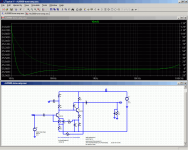
Oh, sorry, that's an LTspice schematic. Just the preamp section.I suppose the file you added was the simulation, I can't open it, would jut a simple screen shot help me understand your process ?
Attachments
Last edited:
Now with tone amp added, plus two outputs (out = tone defeat / out-2 = no defeat). Tone controls tweaked for linear frequency response (set AC component of V1 to "0." and that of V3 to "1." to plot FR). Needed a bit more bass and a hair more mids.
PSRR on tone amp is somewhat better than for the unmodified preamp section but still not exactly great. Seems its basic bias network (the 220k/33k) is the main problem as I originally suspected, RC filtering the supply of that (e.g. 2k2/22u before R23) gives much better results. I normally prefer low-noise bias networks à la Grundig - R/RC between supply and ground, and an R to transistor base tapped from midpoint. That may not be as easy to hack into the existing circuit though. You might just as well split R23 into 100k + 120k, then you can pretty much get away with a 1µ filter cap...
PSRR on tone amp is somewhat better than for the unmodified preamp section but still not exactly great. Seems its basic bias network (the 220k/33k) is the main problem as I originally suspected, RC filtering the supply of that (e.g. 2k2/22u before R23) gives much better results. I normally prefer low-noise bias networks à la Grundig - R/RC between supply and ground, and an R to transistor base tapped from midpoint. That may not be as easy to hack into the existing circuit though. You might just as well split R23 into 100k + 120k, then you can pretty much get away with a 1µ filter cap...
Attachments
Last edited:
I will take it slow !!
So far I installed the 1K resistor and the 100µF cap before R3/R4 and indeed the hiss dimmed a bit but was still clearly present. Than I went for a 91R resistors in series with the zener diode (I had this value laying around and as you said between 33 and a 100 I thought this would do it) and added à 220µF in parallel. This got rid of all the hiss and it sounds very good with headphones but I now have +24v instead of 22 and when I turn up the volume the hiss comes back quite quickly and I now also have a fairly loud hum (also when turning up he volume).
I will tackle the tone amp next but wanted to get these first steps right before going any further.
At this point it would have been interesting to turn TONE DEFEAT on.I will take it slow !!
So far I installed the 1K resistor and the 100µF cap before R3/R4 and indeed the hiss dimmed a bit but was still clearly present.
Higher voltage is expected as Vzener increased to Vzener + 91R * Izener, i.e. about 1.4 V more. That would be a good 2 V more at regulator output.Than I went for a 91R resistors in series with the zener diode (I had this value laying around and as you said between 33 and a 100 I thought this would do it) and added à 220µF in parallel. This got rid of all the hiss and it sounds very good with headphones but I now have +24v instead of 22 and when I turn up the volume the hiss comes back quite quickly and I now also have a fairly loud hum (also when turning up he volume).
That could also be the reason for the hum. You didn't use the phono input to test by any chance? This one uses the -29V, which now may have gone up high enough for the negative reg to temporarily drop out of regulation (input is only -33.5 V nominal, computed output over -31 V). Could you measure input and output voltages? If the differential seems suspiciously low, try temporarily soldering about 220k in parallel to R59 to get voltage back down. Or maybe you've got one more 91R that you could add in parallel to the first one? Or plan C, remove R43 to reduce zener current.
In any case I don't think basic ripple rejection should be any worse than before now, the 220µ should sink remaining hum quite effectively. If I'm wrong I'd have to whip out LTspice again and simulate the whole shebang.
Increased noise when turning up the volume is expected - you've got a 250k volume pot there, that's never going to be a low noise miracle. In the long term you may be better off modifying the headphone resistor dropper, adding about 56-100 ohms (1 W) from L and R output to ground after the 220R series resistors, e.g. at the headphone jack. Stock output level is way more than needed anyway.
Last edited:
I actually did before touching the power supply : when all the settings are at 0 (bass, treble and mid) turning the tone defeat on doesn't affect things all that much, the hiss doesn't change in volume, maybe a little in pitch but only very slightly.
I used the Aux input for testing. at the input I have -40v after R51 (where I should have only -33.5) and +35.6v after R35 and at the output I get +24v/-31.5v.
Concerning the volume pot, several of the AU series amps have 250k pots and I definitely don't have that much noise on them. Before the modifications the volume pot didn't have any influence on the hiss, how come it does now (half way up the hiss is a lot louder than it was before).
Also it's very sensitive too touching, it makes little poping noises when I touch the chassis which it didn't before. The hum gets better when I touch any part of the chassis and worse again when stop touching it.
Last edited:
All quite odd, this.
If the amp is "touchy", maybe you have accidentally disconnected the chassis from circuit ground?
The hiss definitely shouldn't be louder than before. That points towards higher current noise. Possibly you've picked kind of a bad grounding spot for your 100µ, and now it's inserting power supply noise into that. When it comes to old single-sided layouts with thin traces, ground definitely does not equal ground.
Hmm, it looks like F-2604 gets its combined signal and power ground (grrr) from the star ground on F-2598 via F-2602 and F-2603. That's quite the way off. Power supply ground connects to F-2598 via RCA jack ground. There is no dedicated power ground available on F-2604. I don't like that. It's not an issue for the stock circuit, but try to add filtering like we're doing here, and you may be in for a nasty surprise. (The noise current from your 100µ has to travel all the way back along the signal ground connection, which has a decidedly finite, non-zero resistance.) Like I said, ground != ground. Hrmpf.
You may just have to run your own power ground connection from F-2604 back to the regulator (F-2599 post 23, +/-) - ideally along the power lines, keeping a bit of a distance from the real high-impedance sections. Multiple wires of a decent thickness would be ideal, or sort of a flat braid, so you get a certain width (keeps inductance down). Then you can use that to attach your 100µ + 1µ supply filter capacitors. At this point noise should finally turn out as low as predicted.
So much for some quick minor mods, huh?
At this point just brute-force RC filtering the regulator output doesn't sound quite so unattractive any more. Still, I'd always prefer the circuit itself to have some decent local PSRR, being sensitive to supplies that are run through half the device could result in some funny issues.
If you want to rule out the regulator for the time being, consider temporarily shorting your series 91R to bring DC conditions back to where they should be. I don't think it's that though.
Last edited:
I checked and didn't disconnect any ground wires by accident. I did notice though that the signal inputs for F-2604 were very close to the ground wire going to the regulator circuit. I moved those two appart a bit and the hum was already a bit better. Than I decided to install a power cord with an earthing and now I have almost no hum until the volume button is all the way up which seems very acceptable.
I wired the ground for the filtering on F-2604 directly to the ground on the regulator board along the +22v line and the hiss is down as well even when I turn up the volume.
There still is some audible noise compared to other amps but that again I haven't done the filtering for the biasing circuit yet so that will be my next step whenever I'm able to go and buy the right value resistors.
We're getting somewhere thanks to your help so minor or not I'm very grateful. I will let you know how the rest goes when I get there.
Last edited:
Eww. You just turned an IEC Class II device into a Class I one. Make sure you remember this in case you ever have to hunt down ground loops when using e.g. a PC as source.Than I decided to install a power cord with an earthing and now I have almost no hum until the volume button is all the way up which seems very acceptable.
Manufacturers put in extra effort so they can make these as Class II - better insulation, and there's a shield winding in the transformer that just about eliminates primary-secondary electrostatic coupling. This allows device ground to float very well.
If anything, the connection of ground to PE should be relatively weak. Maybe 1 kOhm, possibly in parallel with a pair of antiparallel rectifier diodes (1N54xx or a bridge rectifier wired up accordingly) if you also want some kind of extra protective function.
Phew. So that one worked as predicted. We're getting somewhere.I wired the ground for the filtering on F-2604 directly to the ground on the regulator board along the +22v line and the hiss is down as well even when I turn up the volume.
You could still try running the power ground to F-2598 (star ground) rather than directly to the regulator. Might be marginally less good for hiss but better for hum. You could also choose your RC filter resistor somewhat bigger than 1k (it doesn't have to be quite that small - 2k2-4k7 would still be OK) and reduce noise insertion that way.
It doesn't have to be exactly 100k + 120k. 68k + 150k would also work, or 39k + 180k with a marginally bigger capacitor (2µ2).There still is some audible noise compared to other amps but that again I haven't done the filtering for the biasing circuit yet so that will be my next step whenever I'm able to go and buy the right value resistors.
Does Tone Defeat make a difference now?
- Status
- This old topic is closed. If you want to reopen this topic, contact a moderator using the "Report Post" button.
- Home
- Amplifiers
- Solid State
- Sansui AU 5900 dead channel