I'm trying to design very small brass chassis mono amplifies with either metal BUZ900 or plastic Exicon MOSFETs. Total of 4 transistors per channel with a bias of 100mA per device and 100W into an 8 Ohm load.
If the brass chassis is 3/16" to 1/4" in wall thickness all around and possibly machined out of one solid piece (amp footprint roughly 6"X6"), can I mount MOSFETs directly to the wall, or to the wall via an aluminum angle and skip the heatsink?
Is that size brass body enough to safely dissipate the heat for a 100W design?
Probably not...the quick online calculator for pure copper says that's a ~4C/W with a 100LFM airflow. It depends on how hard you want to push the amp...and what temp you're willing to let the devices get to. The calculator assumes perfectly even distribution of heat on the panel too...so figure a bit higher with 8 devices spread over.
Will it work at low to moderate volumes without dying right away, probably...long term the device temperature will be higher than you probably want.
I worked on fixing a bias issue in an early Krell 5 channel AV amp...they used a 1/4"+ thick aluminum baseplate and a 3/8" thick spreader T for each channel. Each channel had something like 12 output devices. That thing would get RAGING hot...60-70C + after about 3 hours running. It was probably dissipating ~150W total before repair. Two channels responsible for ~100 of that. This total thickness of 5/8" of aluminum was probably 16.5" wide and 12-14" deep. Afterwards it was <60W across all channels. If you tried a 1/3 power test it would thermal out.
Over the years the bias had drifted high two channels. I reset as low as possible until distortion started creeping up, and then checked distortion and distortion spectrum against the factory stock channels, but it still ran warmer than I would have liked.
It will only be 4 devices total, not 8. I have no problem setting bias lower to 70-80mA. I also think it shouldn't hurt things if chassis temp is around 50 Celsius and 60+ C inside.
I think that's raging hot for a bias condition. And that same amp will dissipate quite a bit more than that in use.
http://products.semelab-tt.com/pdf/ApplicationNoteAlfet.pdf
Amplifier Efficiency
You can do it if you want....I just wouldn't.
It will only be 4 devices total, not 8. I have no problem setting bias lower to 70-80mA. I also think it shouldn't hurt things if chassis temp is around 50 Celsius and 60+ C inside.
If that's the idle temp, it will be too hot when you actually play audio through it. It seems like you have moderate thermal 'mass' but little radiation meaning it takes a while to heat up but doesn't get rid of the heat and you do want to keep it cool because it lasts longer cool.
G²
I do it all the time, but my situation is somewhat different.
I make guitar amps, my bread-and-butter model (sold over 10000 of them) uses the back panel as a heatsink, but it's optimized to do so.
1) I use guitar amp style Tolex covered wood cabinets
2) no single chassis, but front and back panels , one for preamp, other for power amp and supply.
3) I mount the power transistors to the back panel, which acts as a heat sink.
4) I have been making amps for more than 40 years, so I can trust that it works.
That said, when I designed the first in the late 60's , early 70's, I followed a then popular rule of thumb : to make a 100W amplifier you need at least 2 power transistors (way back then selected 2N3055H ) , each mounted on a 10x10cm aluminum plate, thickness 2.5mm or better, mounted vertically and in free air (not inside a case) .
My original heat sink cum back panel was a 50cm x 10 cm aluminum piece, 2 mm thick, only the back surface exposed, although the cabinet had top and bottom vents, which later mutated into what I still use: 43 cm x 10 cm , 1.5mm thick overall but with another 1.5mm aluminum rectangle riveted inside, with thermal grease between them.
And the back panel has top and bottom edges bent inside so it still keeps the surface, but is more rigid and self supporting.
So I still meet and exceed old rule of thumb, which seems to work")
Backpanel gets hot around the power transistors, you can touch them but can't leave the palm of your hand for, say, 2 minutes, while front panel stays fresh.
So your design does barely meet minimum dissipation, will work very hot all of it so, as said before, will be uncomfortable, electrolytics inside will last less ...in general too close to the edge for comfort.
In my amps internal parts do not suffer because the cabinet is made for 10 cm panels but since they are bent inside on top and bottom down to 8 cm, I actually have 4 43cmX1cm slots , 2 on top, two on bottom, so air inside is slightly warm but never *hot* .
See that front and back panels are "floating" on a 2 cm too tall cabinet to allow for free airflow.
**Maybe** you can cut a couple slots in your chassis/enclosure and mount somewhere (bottom is fine if you use at least 1 cm high rubber legs) a small fan.
Even a very small and thin "cpu microprocessor cooler" fan the kind which is directly mounted on a small square heatsink attached to the microprocessor itself does a great job.
No need for *high* CFM rating (of course it does not hurt ) but simply renovating hot air out of the enclosure once a minute is fine, what you don't want is static air sitting there heating up continuously.
I always add such small fans to customer amps which suffer from heat, "any air flow is better than none at all".
I make guitar amps, my bread-and-butter model (sold over 10000 of them) uses the back panel as a heatsink, but it's optimized to do so.
1) I use guitar amp style Tolex covered wood cabinets
2) no single chassis, but front and back panels , one for preamp, other for power amp and supply.
3) I mount the power transistors to the back panel, which acts as a heat sink.
4) I have been making amps for more than 40 years, so I can trust that it works.
That said, when I designed the first in the late 60's , early 70's, I followed a then popular rule of thumb : to make a 100W amplifier you need at least 2 power transistors (way back then selected 2N3055H ) , each mounted on a 10x10cm aluminum plate, thickness 2.5mm or better, mounted vertically and in free air (not inside a case) .
My original heat sink cum back panel was a 50cm x 10 cm aluminum piece, 2 mm thick, only the back surface exposed, although the cabinet had top and bottom vents, which later mutated into what I still use: 43 cm x 10 cm , 1.5mm thick overall but with another 1.5mm aluminum rectangle riveted inside, with thermal grease between them.
And the back panel has top and bottom edges bent inside so it still keeps the surface, but is more rigid and self supporting.
So I still meet and exceed old rule of thumb, which seems to work
Backpanel gets hot around the power transistors, you can touch them but can't leave the palm of your hand for, say, 2 minutes, while front panel stays fresh.
So your design does barely meet minimum dissipation, will work very hot all of it so, as said before, will be uncomfortable, electrolytics inside will last less ...in general too close to the edge for comfort.
In my amps internal parts do not suffer because the cabinet is made for 10 cm panels but since they are bent inside on top and bottom down to 8 cm, I actually have 4 43cmX1cm slots , 2 on top, two on bottom, so air inside is slightly warm but never *hot* .
See that front and back panels are "floating" on a 2 cm too tall cabinet to allow for free airflow.
An externally hosted image should be here but it was not working when we last tested it.
**Maybe** you can cut a couple slots in your chassis/enclosure and mount somewhere (bottom is fine if you use at least 1 cm high rubber legs) a small fan.
Even a very small and thin "cpu microprocessor cooler" fan the kind which is directly mounted on a small square heatsink attached to the microprocessor itself does a great job.
No need for *high* CFM rating (of course it does not hurt
) but simply renovating hot air out of the enclosure once a minute is fine, what you don't want is static air sitting there heating up continuously.I always add such small fans to customer amps which suffer from heat, "any air flow is better than none at all".
Last edited:
Member
Joined 2009
Paid Member
doesn't it depend on whether you are going to *use* the 100W or not ? If you bias it a bit cooler (Class AB still) and it's run in an average home environment where you're not be using much of the 100W capacity the amp is capable of - then you might be just fine. Put a thermal cut-out on the casing to kill the power to the amp if it gets too hot for safe skin contact and you're all set.
Total of 4 transistors per channel with a bias of 100mA per device and 100W into an 8 Ohm load.
100W in 8 ohm is 40V peak, 5A peak output current.
You'll require 45V rails minimum.
45V times 100mA is 4.5W idle dissipation per device, 36W total for both channels.
If you wish to use the amp up to full output power, cooling capability would have to be much higher than that.
For a footprint of 6''x6'', I suggest you make the amp case a foot high.
(wall thickness has marginal relevance, air exposed surface is required for cooling)
The entire amp will be tiny machined out of brass, no bigger than 6x6x5, so I believe the surface area of the entire chassis should be counted?
A TO3 without a heatsink has a thermal resistance of 40C/W* (junction to ambient).
4.5W idle dissipation (100mA quiescent and 45V rails) would turn the die of the MOSFET to 180C above ambient temperature.
A BUZ900 dies at 150C.
At 25C ambient, die temperature would have to be less than 125C above that to survive.
Suppose max dissipation for 100W in 8 ohm is 62.5W
Thermal resistance from die to ambient of a single device would have to be 8C/W ** (125 divided by 62.5, times 4 devices)
Footprint of a TO3 is about 1.25 square inch, top and bottom side make 2.5 sqi.
40 (*) divided by 8 (**) makes a factor 5.
5 times 2.5 sqi makes 12.5 square inch heatsink surface for 1 device.
8 devices require 100 sqi surface.
That is, if there would be a linear relationship between thermal resistance and heatsink surface.
There isn't, you'd roughly need twice as much, 200 sqi.
At 6''x6'' footprint, at least a height of 9 inches.
(for a reference : Goldmund Gold Cube, monaural power amp, 100W/8, 5''x5''x5'' hxwxd)
air exposed surface is required for cooling)
Yup, iz all about surface area.
I have a formula somewhere...in^2/W
A TO3 without a heatsink has a thermal resistance of 40C/W* (junction to ambient).
4.5W idle dissipation (100mA quiescent and 45V rails) would turn the die of the MOSFET to 180C above ambient temperature.
A BUZ900 dies at 150C.
At 25C ambient, die temperature would have to be less than 125C above that to survive.
Suppose max dissipation for 100W in 8 ohm is 62.5W
Thermal resistance from die to ambient of a single device would have to be 8C/W ** (125 divided by 62.5, times 4 devices)
Footprint of a TO3 is about 1.25 square inch, top and bottom side make 2.5 sqi.
40 (*) divided by 8 (**) makes a factor 5.
5 times 2.5 sqi makes 12.5 square inch heatsink surface for 1 device.
8 devices require 100 sqi surface.
That is, if there would be a linear relationship between thermal resistance and heatsink surface.
There isn't, you'd roughly need twice as much, 200 sqi.
At 6''x6'' footprint, at least a height of 9 inches.
(for a reference : Goldmund Gold Cube, monaural power amp, 100W/8, 5''x5''x5'' hxwxd)
It's a mono, so it would only have 4 devices per amp. The Gold Cube you posted is the closest to what I have in mind. Small with smooth surfaces on the outside, no heatsink. If they can get 100W out of a 5" cube, then it's doable?
OP's question is whether it is OK to skip the heatsink if he mount output transistors to the amp wall, that is thick and big brass metal. So basically, it is to use brass heatsink as the amp wall.
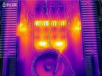
Attached is thermal image of my LM4780 parallel amp with 35V rail. It puts out about 120W at the full power to 4 ohm speaker. You will need good heatsink for your 100W amp at max power. My LM4780 amp is almost at the ambient temperature when it's only 5-10W operating.
Look how hot the chip becomes. It's as hot as rectifiers and resistors in CRC power supply.
Attachments
- Status
- This old topic is closed. If you want to reopen this topic, contact a moderator using the "Report Post" button.
- Home
- Amplifiers
- Solid State
- Is heatsink required for 100W amplifier?