Hi all,
I have taken a backseat on the design side for a while but am in the midst of planning an extremely ambitious monster 6 channel monoblock (besides the shared toroid). This was inspired by a number of high cost parts I came across almost free of change..
There are a few things which are already defined due to availability of parts / constraints, and bits I have purchased. These are namely the single toroidal transformer with ONE set of +/- rails and separate rectification with a total of 12 capacitors (6 sets for each channel).
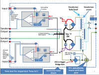
Bonsai has provided a solid platform for attempt to work out the most effective grounding scheme via PM but a few important details were missing and are included in the images attached. The first image shows an effective grounding scheme for a monoblock from Bonsai's guide.
However the traditional T scheme becomes more complex when multiple channels are involved. Some ideas could be have 6 separate T's and join each one to my one star point, have one block of copper across all 6 sets as an H joining then centrally and one individual wire to my star point. Have a separate bars to bridge the capacitors with separate leads the the star point with a row of HHHH's so that each thing could take place at the same point along a giant T e.g 0V protection, speaker GND output etc. Or none of these and isolate each of the 6 T's from one another to give channel GND isolation somehow / some other way?
Any help would be greatly appreciated, please edit the drawings and repost as necessary. The black green and red blocks represent high current terminal screw studs for distribution to all the rectifiers.
I have taken a backseat on the design side for a while but am in the midst of planning an extremely ambitious monster 6 channel monoblock (besides the shared toroid). This was inspired by a number of high cost parts I came across almost free of change..
There are a few things which are already defined due to availability of parts / constraints, and bits I have purchased. These are namely the single toroidal transformer with ONE set of +/- rails and separate rectification with a total of 12 capacitors (6 sets for each channel).
Bonsai has provided a solid platform for attempt to work out the most effective grounding scheme via PM but a few important details were missing and are included in the images attached. The first image shows an effective grounding scheme for a monoblock from Bonsai's guide.
However the traditional T scheme becomes more complex when multiple channels are involved. Some ideas could be have 6 separate T's and join each one to my one star point, have one block of copper across all 6 sets as an H joining then centrally and one individual wire to my star point. Have a separate bars to bridge the capacitors with separate leads the the star point with a row of HHHH's so that each thing could take place at the same point along a giant T e.g 0V protection, speaker GND output etc. Or none of these and isolate each of the 6 T's from one another to give channel GND isolation somehow / some other way?
Any help would be greatly appreciated, please edit the drawings and repost as necessary. The black green and red blocks represent high current terminal screw studs for distribution to all the rectifiers.
Attachments
Last edited:
hi,
adding resistance to the screen of the i/p cable didnt work for me.
instead i added it from sig gnd to psu ov, and a direct connection from the psu to chassis.
that big torrid may throw out noise, so you may want to allow space to enable you to add suitable screening at a latter stage...
adding resistance to the screen of the i/p cable didnt work for me.
instead i added it from sig gnd to psu ov, and a direct connection from the psu to chassis.
that big torrid may throw out noise, so you may want to allow space to enable you to add suitable screening at a latter stage...
For me this layout didnt work with a 2ch dual mono layout.
There is a GND loop if the RCA GNDs are connected both outside and inside the amp.
Even I dont see the way the 15R signal GND resistor could work.
This signal should drive the amp's input directly.
In my layout the channels have no common points at all,
but only at the input RCA GNDs and there is 0 hum...
A mono block amplifier is ONE Channel in ONE enclosure.
A multichannel amplifier is multiple channels in one enclosure.
One cannot have a multichannel monoblock.
The "grounding" of a mono block amplifier is fairly simple. There is ONLY one channel connected to the Chassis.
As soon as one locates multiple channels inside the enclosure, then that opens to the possibility of loops in the multiple connections to the enclosure.
Last edited:
That diagram looks likes Bonzai's from his amplifier wiring guide.Hi all,
I have taken a backseat on the design side for a while but am in the midst of planning an extremely ambitious monster 6 channel monoblock (besides the shared toroid). This was inspired by a number of high cost parts I came across almost free of change..
There are a few things which are already defined due to availability of parts / constraints, and bits I have purchased. These are namely the single toroidal transformer with ONE set of +/- rails and separate rectification with a total of 12 capacitors (6 sets for each channel).
Bonsai has provided a solid platform for attempt to work out the most effective grounding scheme via PM but a few important details were missing and are included in the images attached. The first image shows an effective grounding scheme for a monoblock from Bonsai's guide.
However the traditional T scheme becomes more complex when multiple channels are involved. Some ideas could be have 6 separate T's and join each one to my one star point, have one block of copper across all 6 sets as an H joining then centrally and one individual wire to my star point. Have a separate bars to bridge the capacitors with separate leads the the star point with a row of HHHH's so that each thing could take place at the same point along a giant T e.g 0V protection, speaker GND output etc. Or none of these and isolate each of the 6 T's from one another to give channel GND isolation somehow / some other way?
Any help would be greatly appreciated, please edit the drawings and repost as necessary. The black green and red blocks represent high current terminal screw studs for distribution to all the rectifiers.
It is wrong.
I have told Bonzai it is wrong.
I have offered to discuss this with him and some months ago he agreed. He has since confirmed that he is too busy to respond. As a result the error still appears in his guidance documents.
Do not copy Bonzai's layout, it is wrong.
The same error is repeated in his NX amplifier literature.
But the error is NOT in his NX PCB. He has located the added resistor HBRL and HBRR in the correct trace.
I have told Bonzai this as well and still he has not responded.
Read Joffe for the correct location of HBRL/HBRR
Last edited:
A mono block amplifier is ONE Channel in ONE enclosure.
A multichannel amplifier is multiple channels in one enclosure.
One cannot have a multichannel monoblock.
The "grounding" of a mono block amplifier is fairly simple. There is ONLY one channel connected to the Chassis.
As soon as one locates multiple channels inside the enclosure, then that opens to the possibility of loops in the multiple connections to the enclosure.
Point taken it was a bit silly and technically incorrect - I took it from the independent rectification and capacitors. I have modified the thread title as such.
Andrew thank you very much for pointing out this error. I have reviewed the paper and understand the resistors must be placed at the input. Are there any other significant oversights you are aware of in his guide?
I did a bit of reading this afternoon on LF EMI through non ferrous metals and may change the aluminium potting to a wrap of mu-metal, but that's for another thread..
Can anyone suggest the most effective grounding method for the 6 sets of capacitors?
Thanks,
Matt
Have you read Joffe?
Bonzai appears to have used his advice in laying out the HBRL/HBRR on the NX PCB.
There are no other "errors" in his guidance, that I am capable of spotting.
But I would put a lot of emphasis on connecting signals with TWO wires of very LOW LOOP AREA.
And try to minimise any references to a "ground".
"ground" just adds to confusion because so many use the same word for everything.
I would not use mu metal.
It's characteristics change when you bend it, eg from a flat strip to a circular loop.
Use a thick chunk of iron or steel.
A very short length of steel pipe would work very well around an uneven source of magnetic emi.
I have not experimented with this, but if it's good enough to be adopted by Sugden, then they must have some evidence that it works.
Why do you want to "ground" your capacitors?
RF filtering capacitors would be connected direct from incoming cable core to Chassis using the shortest possible lead length.
The PE needs to be connected to the enclosure, if it's conductive.
What else needs to be connected to the enclosure?
Attachments
Last edited:
You still haven't told us how many secondaries you have, and how many rectifiers you intend to use. Unless you have separate secondaries for each amp and separate rectifiers you can't separate the grounds, so you will have just one T i.e. one PSU driving six amps. I assume that by "grounding" you mean 'how can I arrange the return currents to the rectifiers to avoid buzz'.matt09 said:Can anyone suggest the most effective grounding method for the 6 sets of capacitors?
I understand that mu metal saturates easily, so is useless for shielding power transformers. Much better to use distance, and small loop areas, to reduce unwanted magnetic coupling.AndrewT said:I would not use mu metal.
It's characteristics change when you bend it, eg from a flat strip to a circular loop.
My 15R is indeed in the wrong place - apologies. But that is the ONLY error in my layout- nothing else.
As I have also made clear, these are a number of techniques to wiring up an amp - for example Self bonds his RCA's as they come into the chassis via a wire to the mains earth and connects this to the star ground.
In my approach, I have 'T'd' off the speaker return and signal grounds - this guarantees you wont get charging currents from the filter caps and also that you won't get common impedance coupling from the speaker return currents into the signal grounds.
My suggestion for a 6 channel amp is:-
1. use a single transformer with two isolated secondaries
2. rectify and smooth the secondaries independently.
3. connect the + of one to the - of the other to create a split supply
4. 'T' off from where you connected the two supplies (to avoid the charging currents contaminating the signal and speaker return grounds) - about 0.5 - 1cm is fine
5. The speaker returns should come off this 'T' as well as the decoupling return from the amplifier boards (1 wire for each board - no daisy chaining)
6. 'T off of this for the signal ground - again 0.5 - 1cm should be fine
7. connect the chassis to the main star ground. Only have one connection point to the chassis. Use a meter to make sure all parts of the chassis are connected - sometimes paintwork and anodizing result in parts of the chassis not being connected. Make this point the same point where you connect the incoming power receptacle earth - usually its just 5-6 cm away from the receptacle earth.
8. use a fused IEC mains receptacle - safe and looks neat
I usually get a flux band (='belly band') and a screen included if I get a transformer custom would - it makes a difference so I would always encourage you to do that.
As mentioned by PM to Mathew, you have to minimize common impedance coupling and loop areas to get rid of noise
1. make sure the wires to the rectifiers and to the capacitors are tightly twisted together
2. tightly twist the +- and speaker return wire together (this is very much layout dependent - some wiring schemes don't lend themselves to this approach)
3. for the decoupling return from the amplifier PCB's, I would recoment you also include this in the twisted +- and speaker return wires
4. Keep the input wiring away from current carrying wires
5. for the mains wiring to the power switch, make sure the live and neutral (= hot and neutral for US readers) are closely coupled. I use a piece of sheathed mains wire which is good for safety, and ensures the coupling is good.
6. you may have to experiment a bit with cable dressing to get the noise really low. I use a pair of headphones connected to the speaker outputs. You can then move the bundled (i.e. twisted together wires mentioned above) to get a null.
My nx, sx and e-Amps are very, very quiet. However, there is more than one way to skin a cat - this is what works for me.
")
As I have also made clear, these are a number of techniques to wiring up an amp - for example Self bonds his RCA's as they come into the chassis via a wire to the mains earth and connects this to the star ground.
In my approach, I have 'T'd' off the speaker return and signal grounds - this guarantees you wont get charging currents from the filter caps and also that you won't get common impedance coupling from the speaker return currents into the signal grounds.
My suggestion for a 6 channel amp is:-
1. use a single transformer with two isolated secondaries
2. rectify and smooth the secondaries independently.
3. connect the + of one to the - of the other to create a split supply
4. 'T' off from where you connected the two supplies (to avoid the charging currents contaminating the signal and speaker return grounds) - about 0.5 - 1cm is fine
5. The speaker returns should come off this 'T' as well as the decoupling return from the amplifier boards (1 wire for each board - no daisy chaining)
6. 'T off of this for the signal ground - again 0.5 - 1cm should be fine
7. connect the chassis to the main star ground. Only have one connection point to the chassis. Use a meter to make sure all parts of the chassis are connected - sometimes paintwork and anodizing result in parts of the chassis not being connected. Make this point the same point where you connect the incoming power receptacle earth - usually its just 5-6 cm away from the receptacle earth.
8. use a fused IEC mains receptacle - safe and looks neat
I usually get a flux band (='belly band') and a screen included if I get a transformer custom would - it makes a difference so I would always encourage you to do that.
As mentioned by PM to Mathew, you have to minimize common impedance coupling and loop areas to get rid of noise
1. make sure the wires to the rectifiers and to the capacitors are tightly twisted together
2. tightly twist the +- and speaker return wire together (this is very much layout dependent - some wiring schemes don't lend themselves to this approach)
3. for the decoupling return from the amplifier PCB's, I would recoment you also include this in the twisted +- and speaker return wires
4. Keep the input wiring away from current carrying wires
5. for the mains wiring to the power switch, make sure the live and neutral (= hot and neutral for US readers) are closely coupled. I use a piece of sheathed mains wire which is good for safety, and ensures the coupling is good.
6. you may have to experiment a bit with cable dressing to get the noise really low. I use a pair of headphones connected to the speaker outputs. You can then move the bundled (i.e. twisted together wires mentioned above) to get a null.
My nx, sx and e-Amps are very, very quiet. However, there is more than one way to skin a cat - this is what works for me.
Last edited:
For me this layout didnt work with a 2ch dual mono layout.
There is a GND loop if the RCA GNDs are connected both outside and inside the amp.
Even I dont see the way the 15R signal GND resistor could work.
This signal should drive the amp's input directly.
In my layout the channels have no common points at all,
but only at the input RCA GNDs and there is 0 hum...
Indeed - as I note in my write-up, the RCA connectors should NOT be connected to the chassis where they come into the amplifier. This will almost guarantee hum and noise problems (I thought that was clear in my write-up?)
The 15R resistor is shown in the wrong place - it should be in the wire from the signal input to the power supply ground. The 15R resistor is designed to reduce significantly any ground currents (=earth loop) flowing in the interconnect cables. The ground loop currents instead then flow via the safety earth connections. In double insulated products, there is often no earth connection (see your average CD player for example) and the earth loop currents are in general non-existent or very low and don't cause a problem.
If you wire up as I have should, you will have no common point between the two channels other than at the star ground, and where you take off the power wiring.
Last edited:
Some thoughts on separate capacitor banks for each channel of a single bank of capacitors.
In practice, there will be little to be gained by splitting the reservoir capacitors up and doing a separate bank for each amplifier module. The PSRR of the amplifiers should be sufficient to provide adequate power supply rail ripple rejection. A typical VFA will give upwards of 60 dB at LF, with 70~80 dB more the norm. If minimizing cross coupling between amplifiers is a real concern, a smarter way to deal with it is to use a cap multiplier - see the e-Amp, Dadod's designs and also Ostripper's amplifiers for example.
By splitting the reservoir caps up, you increase the loop areas and the chance to radiate more noise. Secondly, grounding and dealing with the charging currents is also more complex.
Using a single reservoir cap bank means you can keep the whole rectifier + capacitor bank physically smaller and reduce noise coupling.
Bonsai, when you combine the input(+feedback) and decoupling GNDs then the current to/from the decoupling capacitors will create an error voltage between the feedback loop and the speaker return.
Connect the speaker GNDs to the local GND of each channel and connect the local GNDs to the T.
Another option would be to leave the speaker GNDs connected to the T and use separate connections for the input(+feedback) and decoupling GNDs.
This still leaves you with the problem of where to connect the output filters.
I separated the speaker return, board decoupling and signal grounds - I think we are saying the same thing. But, separating the grounds like this to avoid common impedance coupling also means the loop areas are increased - so you have to make sure the bundles are well twisted and dressed to keep the loop areas minimum.
On my amps I run a separate ground wire from the Zobel to the PSU speaker star ground to avoid injecting HF currents into the amplifier module ground. This wire is bundled with the +- and ground wire bundles.
On my amps I run a separate ground wire from the Zobel to the PSU speaker star ground to avoid injecting HF currents into the amplifier module ground. This wire is bundled with the +- and ground wire bundles.
Bonsai, I think we are saying the same thing. That is an awful lot of wires running from the PSU to the six amps.
If you connect both of the speaker wires directly to each channel board you will reduce the amount of (GND) wires by two per channel and have smaller loop areas too.
If you connect both of the speaker wires directly to each channel board you will reduce the amount of (GND) wires by two per channel and have smaller loop areas too.
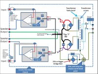
The 15R resistor is shown in the wrong place - it should be in the wire from the signal input to the power supply ground.
The 15R resistor is designed to reduce significantly any ground currents (=earth loop) flowing in the interconnect cables. The ground loop currents instead then flow via the safety earth connections.
Is this version correct?
Attachments
Yes, that's the correct location for HBRR and HBRL.
Look at the loop from Right RCA barrel to Left RCA barrel.
When a Source is connected to these inputs that loop gets closed.
The total resistance in the loop is the resistances of all the wires cables and traces plus the HBRL+HBRR. The traces, wires & cables coming to somewhere from 100milli-ohms to 1ohm. HBRR+HBRL adds 2ohms to 30ohms to that.
i.e. the loop resistance increases from typically 0r3, to 30r3.
The interference current flowing around the loop DECREASES by ~40dB and the interference voltage from the Source RCA barrel to the amplifier Sig GND pad due to that current DECREASES by ~40dB.
Notice that adding HBRR & HBRL does not eliminate the interference. It merely reduces it, hopefully below audibility.
This is the same resistor that Leach describes in his Lo Tim papers.
Last edited:
Mark,
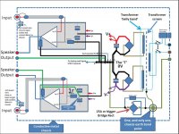
the lower half of the post18 diagram shows the Zobel returning to the local supply rail decoupling.
I think this shorter route help reduce the impedances and thus helps amplifier performance, compared to the longer route shown in the upper half of the diagram.
I don't think that "attaching" the speaker return to the Zobel return makes much difference. The speaker current has to return to the PSU and the length of that route cannot be shortened.
But there is a more subtle difference.
The LOOP AREA of the speaker flow and return must be minimised and running the speaker return next to the ROUTE of the speaker current flow from PSU to speaker terminal should be implemented along the whole Flow and Return Route.
Finally, note that my description (post18) for the interference current attenuation applies to post17 and to post19 upper and post19 lower.
Last edited:
- Status
- This old topic is closed. If you want to reopen this topic, contact a moderator using the "Report Post" button.
- Home
- Amplifiers
- Solid State
- 6-channel-amplifier-grounding