Hi Scott,
Just match the emitter degeneration resistors with your meter. That should do it. But the actual idea is to let you know how close your matches can be.
This was discovered when a near perfect matched pair generated an offset in a "blameless" type amplifier. Further checking uncovered a pair of emitter degeneration resistors that were off by 1/2 their 5% tolerance. Fixing the match corrected the balance issue. Lesson learned.
Be aware that some designs have built in DC offset. You can work out the expected offset by multiplying the base current by the resistor used for the DC return path. Do that for each side and you should come up with the same number. The two base currents will be the same as long as the transistors are matched, close enough to work as an assumption anyway. So for example, if both sides of the diff pair are supposed to have 37 mV of DC offset, the pair is matched. If one side is 45 mV and the other 25 mV, the amplifier will have a DC offset that is designed into it. In this case there isn't a problem to fix and the amplifier is just that way. You would probably have to simulate the circuit to get the actual circuit to find out what the actual DC offset should be.
-Chris
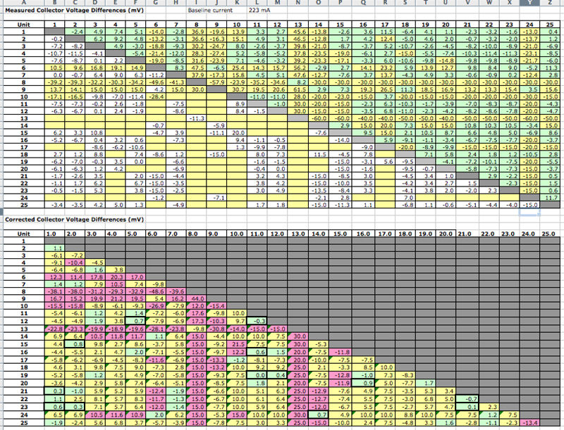
OK, after many hours of testing all combinations of 25 transistors, in both test jig positions, I have found a number of good matches, and a few really bad devices.. I might add, that this was very time consuming. With 25 devices there are as many as 625 separate measurements to be made.
Remember, I am using an approach in the jig that swamps out any minor offsets by testing the paired in opposing spots in the jig. As noted above, the resting corrected offset removes any residual errors caused by the jig. So I am pretty confident in these numbers.
The baseline tail current is about 2.23 mA
Here are the numbers. The top grid is the actual recorded values. You will see I didn't bother to test all opposing combinations (thus, slightly fewer than 625 tests), because some were so bad in position A that testing in position B would never correct them to be better than a +/- 10 mV match (an arbitrary bar I set).
It turned out that bar was pretty low, since I have many within 2 mV, and, more than a few that match to less than 1 mV, and some devices that are nearly perfectly matched, 1 mV across the 100 Ohm load resistor represents .01 mA difference in collector current between the two devices.. yes, that's a match within 10 micro amps at a collector current of about 1.1 mA.. or better than 1%. Matches less than 0.5 mV are better than 0.5%
Now on to test the MPSA13's
Hi Scott,
Your results are similar to mine. These are all from one lot - right?
-Chris
No. It was two lots. One lot of 20, and one lot of 5. Mostly good matches, with a few outlier devices, and a handful of very good matches
As promised, here are the CAM files for the Beta Matcher circuit.
https://www.dropbox.com/s/j392atu5bs3uzts/Archive.zip?dl=0
https://www.dropbox.com/s/j392atu5bs3uzts/Archive.zip?dl=0
Last edited:
Hi Scott,
The link doesn't work. The directory is also local access only, no one else has permission.
The link to the file results in a
I hope that helps.
Best, Chris
The link doesn't work. The directory is also local access only, no one else has permission.
The link to the file results in a
If you remove the file name from the link so you are in the directory, you get404: Page not found
This error is generated when there was no web page with the name you specified at the web site.
403: Forbidden
This error message is generated when the web server is trying to access a file that does not exist or has been configured incorrectly
I hope that helps.
Best, Chris
Chris;
I noticed that your matcher includes capacitors that were not included in the diagram. I did not include them on my board. I assume these are just electrolytics and .01 uF bypass caps across the voltage rails. right?
The board works great without them, but let me know if you think I should add them.
Scott
Hi Scott,
Those capacitors prevent the transistors from oscillating. You just never know.
When I do schematics, I'm afraid that the capacitors are usually left off unless I make an effort to include them. When I design PCBs or wire circuits up, I always include capacitors for power bypass so that everything behaves itself.
I would include them if I were you. Boards made already can have the capacitors mounted under the PCB. So no loss with the boards.
-Chris
Edit: Dropbox! Arrrrgh! I wasn't using that service, so I let it lapse.
As promised, here are the CAM files for the Beta Matcher circuit.
https://www.dropbox.com/s/j392atu5bs3uzts/Archive.zip?dl=0
PLEASE NOTE:
The PCB files I loaded at Drop Box contained an error. I identified this when I went to put the caps on the board. DO NOT USE IT until I replace it with the corrected version.
If you DID use it swap the emitter and collector leads on the PNP current source...
I have not yet taken the time to figure out how this may have impacted the matching work I did a few weeks ago.
Last edited:
OK! So I just scored another pair of GFA 565's on eBay. These ones "supposedly" have had the caps replaced, but I'll believe that when I test the amps.
My plan is to build out a set of new control boards for my small armada of amps, pick the best three and probably sell the others. The amp I have been working on for a while (got slowed way down by work and the need to build a matcher and then match the devices) has all new output devices, So I'll probably keep that one for my sub woofer, and then select the two remaining best ones for the right and left channels.
My plan is to build out a set of new control boards for my small armada of amps, pick the best three and probably sell the others. The amp I have been working on for a while (got slowed way down by work and the need to build a matcher and then match the devices) has all new output devices, So I'll probably keep that one for my sub woofer, and then select the two remaining best ones for the right and left channels.
@cogeniac, you mentioned earlier in the thread that a previous tech had replaced the KB362 diodes with a string of 4148's or something... You said you resolved the issue, but I don't recall if you mentioned how. Pardon me if you know all this already... But, I believe I have these diodes figured out. They are "Stabistor" diodes, and are used as low-voltage references, and they're more stable in Vf due to the fact that they are avalanche, not tunnel diodes. The KB362 has three diodes in one case, and the 262 has two. Each P-N junction is has a Vf=0.7v, so the 262 is1.4V at 10ma, and the 362 is 2V.
A string of 4148's or something will work, but the Vf will vary a lot more.
I believe the only available replacement is the surface-mount Central Semiconductor CMXSTB200, 300 and 400.
Anyways, I wrote more over at this thread...
http://www.diyaudio.com/forums/solid-state/193699-adcom-gfa-565-diodes.html
I'm still not 100% sure of all this, but I will be trying these parts in a customer's GFA-565 within the week.
@cogeniac, you mentioned earlier in the thread that a previous tech had replaced the KB362 diodes with a string of 4148's or something... You said you resolved the issue, but I don't recall if you mentioned how. Pardon me if you know all this already... But, I believe I have these diodes figured out. They are "Stabistor" diodes, and are used as low-voltage references, and they're more stable in Vf due to the fact that they are avalanche, not tunnel diodes. The KB362 has three diodes in one case, and the 262 has two. Each P-N junction is has a Vf=0.7v, so the 262 is1.4V at 10ma, and the 362 is 2V.
A string of 4148's or something will work, but the Vf will vary a lot more.
I believe the only available replacement is the surface-mount Central Semiconductor CMXSTB200, 300 and 400.
Anyways, I wrote more over at this thread...
http://www.diyaudio.com/forums/solid-state/193699-adcom-gfa-565-diodes.html
I'm still not 100% sure of all this, but I will be trying these parts in a customer's GFA-565 within the week.
As far as I understood them, they are varistors, which seems odd, since they are never reverse biased, so the negative side of varistor curve would be meaningless.
I have had good luck replacing them with NTE 605 varistors, but honestly. I have not checked closely to see if they match the characteristics of the KB362/262.
Your theory makes more sense, since in the diode stack on the Adcom control board, the forward voltage would be the most critical aspect.
I have a few original KB devices. I'll take some measurements and see if your theory is correct.
I have a few original KB devices. I'll take some measurements and see if your theory is correct.
Yes, please do! This latest pair of 565's I am working on do not have the usual epoxy-blob style KB262 and 362, but rather un-marked black and pink diodes. This is a late serial number, so I suspect they became unavailable. They're not marked, but I guess they're 1N4156 and 1n4157 or BZV86. Here's the Vf's I measured...
Mystery Stabistor #1 (KB262 position, two-junction diode)
0.1ma = 1.05v
1ma = 1.18
3ma = 1.25
5ma = 1.29
10ma = 1.35
Mystery Stabistor #2 (KB362 position, three-junction diode)
0.1ma = 1.55v
1ma = 1.74
3ma = 1.84
5ma = 1.9
10ma = 2.0
OK, I am more and more confident this is the answer. I received the CMXSTB200 and 300 diodes, and the measurements match the original diodes closely.
CMXSTB200
0.1ma = 1.0v
1ma = 1.2
3ma = 1.32
5ma = 1.37
10ma = 1.44
CMXSTB300 (Actually STB400 with one diode unused)
0.1ma = 1.5v
1ma = 1.8
3ma = 1.98
5ma = 2.05
10ma = 2.17
Here's how I converted the surface-mount diodes to through-hole...
I soldered thin leads to them
Then a blob of JB Weld putty epoxy.
I'll be trying these diodes in an amp soon, and I'll update this thread, as well as the other thread where this is being discussed...
http://www.diyaudio.com/forums/solid-state/193699-adcom-gfa-565-diodes.html
Looking at the diode stack in the schematic, I see that the total voltage drop is about 80 volts (85 volt rail, and about 4-5 volts in diode drops). The resistance in that stack is about 39.25K ohms, so the total current is about 2 mA, not 10.
That puts the drops for your Stabistors at about 1.2 v and 1.8 v, but your parts seem to match over the range, so this looks like a good solution.
I always wondered about the "Varistor" aspect. A varistor has a dual I-V curve, so it acts like two parallel diodes with opposite polarity, that is it has a negative I-V part and a positive one. In this circuit all of the current is forward, so a varistor would be useless. In addition, the match between the diodes in the stack (top matched with bottom) is important for maintaining the DC balance bias, which translates to DC offset.
Nice work! For a more truly representational equivalent, I think you should paint the epoxy covers properly though (half black and half orange for one, and half black half cream for the other!) :-D
Bought a small pile of the 200 and 400 devices..
I think I'll do one more run on my new control board PCB (need to fix the heat sink hole position anyway, and I'll lay out the board with the pinout for the SMD devices..that will avoid the lead soldering and potting..
I really appreciate your sleuthing. This was the only real mystery left on this board...
Thanks!
S
Awesome! Thanks so much for your tech expertise on this too. I'm still wondering if the epoxy-blob-cased KB362 and 262 measure the same too. Pretty sure they will, but I couldn't find a proper datasheet, just some specs in a chart.
They do look like electric rabbit turds. I just marked cathode with a sharpie stripe. It's hard to make the blobs small. Maybe a better potting method would be making candy dots with thick clear epoxy.
I like the SMD circuit board idea. You could redesign the whole board to use SMDs. That would be a lot of work.
I'm curious about other applications for these stabistors. They seem like they would make perfect voltage references for current sources like those supplying a long-tail-pair, replacing the usual string of 4148's. Might they be lower noise because of their better Vf stability? The kind of stability they seem to have is in the low-frequencies. You can see it in the way the meter barely varies when measuring Vf. I wonder if they are also more steady in the HF realm.
Last edited:
The dominant real estate elements on the control board are the resistors, and I'd avoid using carbon chip resistors in that application, so an SMD version wouldn't really do much. However, it's easy to lay out the board to take these diode devices without needing to do the potting..
S
S
- Home
- Amplifiers
- Solid State
- Yet Another Adcom GFA-565 Thread