25Vac into 4ohms is equivalent to 156W and draws a maximum current of 8.84ApkAt 4 ohms and 25 volts at the amplifier's output turns on protection...How to disable protection?
Maybe the protection is telling you to turn the input down !
330W into 8r0 gives a maximum output current of 9.2Apk
Your 4r0 test load is getting very close to this same maximum current.
But due to the lower output voltage the Vce is higher than when driving the 8r0 load. That higher Vce increases the stress on the transistor.
The protection may be correctly limiting the output into a 4r0 load.
Again, maybe the protection is telling you to turn down the input.
No problem, I held off posting because of possible copyright but I don't think that is really an issue. Besides, I get loads of useful advice on diyaudio from AndrewT and many others so happy to give something back. I cannot guarantee this is 100% correct but it should be pretty close. I had to substitute a string of diodes for the 3V zener on emitter leg of 2SC2383 and there may be other component substitutions to match available LTspice or other library parts.
Attachments
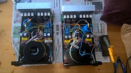
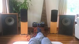
Finished project PR-800
Used 500VA 35-0 35-0 transformers to build 2 x monoblocks using these bad boys. They're not ultra hifi but sound great all the same. I'm having the opposite problem to others in this thread; in getting the input correct, I think i'm going to need a pre-amp stage as the standard pre-out from my system doesn't seem to drive them at full whack. I'm running them into 8ohm with +/- 55v supply rails and they should be deafening me but they're not.
I'm currently using both a speaker protection board and a huge output cap. I dare not directly couple my nice speakers just yet. i need to make sure that they'll behave. Left them playing quietly for 48 hours and they're still ok so they seem stable enough.
Easy project for beginners. Folding steel into DIY clam-shell case was the hardest part.
Attachments
Hi,
I'm very interested in building an amplifier for a sound system I'm going to put together the next couple months or so. Would you be willing to provide a parts list of what is needed in addition to the PR-800? i'll be doing the same set up, a pair for 2 channels to 2 speakers. Thanks!
I'm very interested in building an amplifier for a sound system I'm going to put together the next couple months or so. Would you be willing to provide a parts list of what is needed in addition to the PR-800? i'll be doing the same set up, a pair for 2 channels to 2 speakers. Thanks!
Additional components
In addition to the amplifier modules themselves (one per channel);
You'll need a +- 55v power supply.
Speaker protection boards (ebay <£5)
Output capacitors 10,000 uf 300v (one per channel)
A 12v power supply for the bias input
For the power supplies i used:
35-0 35-0 torroid 300VA
2 x bridge rectifier
2 x 10,000 uf 100v capacitors for smoothing
4 x 4uf capacitors for smoothinh
2 x 100nf capacitors for smoothing
12-0 12-0 torroid 15w for the bias and speaker protection
Hello guys
Thank you Roclite for the schematics. I was also pissed off by the need of this extra transformer. After checking your schematic, I decided to add a resistor between GND and the anode of D5. Any value in the 1 to 10 Kohm does the result : the amp now works with its normal +V/GND/V- supply only. Is what I have done is correct and safe in the long run ?
Thanks
I would advise using a separate bias supply. It only needs to be a small VA transformer and i used the 2nd winding from a 12-0-12 bias transformer to power my speaker protection circuit. That way the speakers shut off quickly without waiting for the main rail with it's huge smoothing caps to colapse.
Hi , I just finished building a retrofit of this amp into an old amplifier chassis that has dual power transformer , I read that this have a over current protection. My Questions are :
1. Does this also have output short circuit protection?
2. Do the relay with it's corresponding circuit offer DC speaker protection in case of amplifier failure?
Thanks
1. Does this also have output short circuit protection?
2. Do the relay with it's corresponding circuit offer DC speaker protection in case of amplifier failure?
Thanks
Hi Marchel,
If you check the published schematic in previous post, PR800 has an output stage current detection circuit around PRO+/PRO- connected to an SCR latch U1. When the SCR is latched by an over-current condition, Q7 CCS is turned off and the amplifier shuts down until power is reset. This circuit has proven to be problematic for some users. I still don't see the need for the separate transformer power supply and a simple resistor bias circuit as described by musicseeker would probably be ok. I think the existing circuit is much more about ripple reduction for the CCS as the main power supply capacitors will remain charged regardless of how the SCR is tripped, discharging when the amplifier is in fault condition. Any additional speaker protection relay circuit should provide full speaker protection as it is normally tripped by DC detection on the amplifier outputs.
If you check the published schematic in previous post, PR800 has an output stage current detection circuit around PRO+/PRO- connected to an SCR latch U1. When the SCR is latched by an over-current condition, Q7 CCS is turned off and the amplifier shuts down until power is reset. This circuit has proven to be problematic for some users. I still don't see the need for the separate transformer power supply and a simple resistor bias circuit as described by musicseeker would probably be ok. I think the existing circuit is much more about ripple reduction for the CCS as the main power supply capacitors will remain charged regardless of how the SCR is tripped, discharging when the amplifier is in fault condition. Any additional speaker protection relay circuit should provide full speaker protection as it is normally tripped by DC detection on the amplifier outputs.
HI roclite ,
Thank you for your reply , But I'm still not sure whether this amp have a short circuit protection , Meaning if I accidentally shorted the output wires , The Amp won't burn , That's what I wanted to know without learning the hard way")
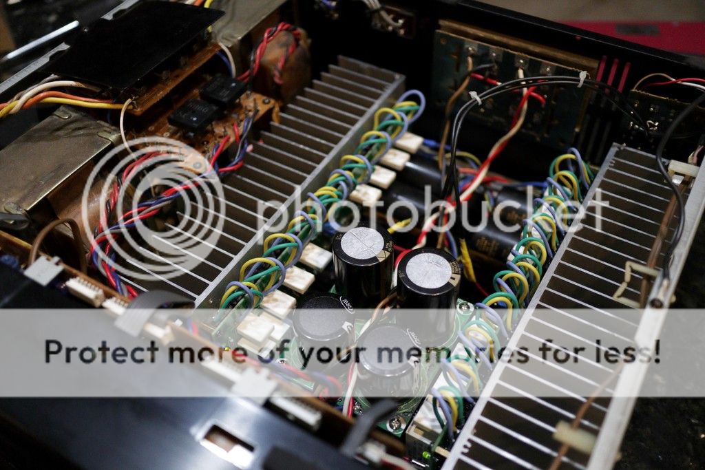
BTW , This is my amplifier , It is an updated version with 2 x 10,000uf elna caps. instead of the 4 caps in the original version of the pr-800 board, I use my old Onkyo M504 chassis and transformers , I just finished it and playing some tunes in my test music system as of this writing.


Thank you for your reply , But I'm still not sure whether this amp have a short circuit protection , Meaning if I accidentally shorted the output wires , The Amp won't burn , That's what I wanted to know without learning the hard way
BTW , This is my amplifier , It is an updated version with 2 x 10,000uf elna caps. instead of the 4 caps in the original version of the pr-800 board, I use my old Onkyo M504 chassis and transformers , I just finished it and playing some tunes in my test music system as of this writing.


Hi Marchel,
Great job on your amp!.The PR800 on-board over-current detection should protect the amplifier from output short-circuit but I have never tested it or even powered up the amplifier. Hopefully, someone can confirm that the circuit works effectively, having tested or experienced this on their own amplifier.
Great job on your amp!.The PR800 on-board over-current detection should protect the amplifier from output short-circuit but I have never tested it or even powered up the amplifier. Hopefully, someone can confirm that the circuit works effectively, having tested or experienced this on their own amplifier.
- Home
- Amplifiers
- Solid State
- PR-800 ClassA/AB Amplifier Kit