I have an old Marantz 240 power amplifier with a blown output transistor. For the last few years its been sitting on the shelf, just begging me to convert it into a Leach amp. The transformer is correct, and the heatsinks are set up for 4 TO-3 devices per channel. I've finally decided to get busy on it.
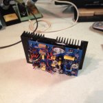
The Marantz PCBs were mounted on the back of the heatsink, as shown in the picture below. I could have made the original Leach v4.5 PCBs work, but since I procrastinated so long that Professor Leach has passed on, and his boards seem to be no longer available, I have made a new layout in a (larger) board size dictated by the mounting holes of the original Marantz modules. I have tried to copy the original component placements and circuit tracks, with some minor changes. One such change is to take advantage of the larger board size to add a TO-126 footprint in parallel with the TO-39 can footprint. This will allow me to experiment with different VAS transistors.
Sorry to ramble on so. I'm interested in comments on this new layout, also below. PCB layout is not my strong suit, but I've followed Leach's original layout pretty closely. I'm just wondering if any of the experts out there have any suggestions.
Also, if anyone is interested, I'll be happy to share the DesignSpark files and/or the Gerbers.
Best regards to all,
Mike
Attachments
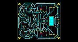
Stick to the design and it should not only work well, but look really good, too.
Making my Leach amplifiers look professional was always a problem--I just kept the chassis out of sight. I've been using MJ21193/94 output transistors for years with excellent performance but my current version uses ONSemi Thermatrak output transistors in the plastic packs. Those fast devices seem to deal better with complex loud transient music, it just sounds 'cleaner'.
Bob Cordell's audio amplifier book gives a lot of insight into design, I've implemented his suggestions on star grounding by distancing the transformer center tap from the signal ground. Maybe consider that after getting the amplifier to work with the Leach design.
I considered at one time sourcing the original circuit boards, but after the 2008 Great Republican Recession I'm doing well just to keep my audio system and test bench.
Unfortunately, I think we're on our own for PCBs. I got exactly one prototype board laid out for plastic case transistors, and it's no longer available. The original artwork is available on Leach's web page:
http://users.ece.gatech.edu/mleach/lowtim/graphics/pcb_corrected.pdf
At one time I thought a gerber file of the artwork was on his site, but check and see if the usual small-run PCB makers can work with a pdf file.
The ThermakTrak power transistors I used are NJL3281D and NJL1302D; mind the layout because this is a five-terminal package and the pinouts are not the same.
http://www.onsemi.com/pub_link/Collateral/NJL3281D-D.PDF
Mouser and Digikey still stock these and other ONSemi transistors; they should also stock all the transistors and diodes needed.
Thanks,
I'm looking for a design with flat pack transistors. I do not like to wire the transistor to a pcb.
Looking this now : The Leach amp 200W amplifier
JG
I'm looking for a design with flat pack transistors. I do not like to wire the transistor to a pcb.
Looking this now : The Leach amp 200W amplifier
JG
Mike, I hope others chime in. I too have a dead Marantz 250 that I was planning to bring back to life. The Leach amp seems like a great option.
I was thinking of stuffing in some Hafler bits but I have two DH200s on the shelf. Probably don't need a third.
Please let us know how it goes for you.
rick
I was thinking of stuffing in some Hafler bits but I have two DH200s on the shelf. Probably don't need a third.
Please let us know how it goes for you.
rick
- Status
- This old topic is closed. If you want to reopen this topic, contact a moderator using the "Report Post" button.