I promised to show my simulations of ripple rejection improvement using the soft start circuit deemed "wrongly inplemented" by Fred and a 10uf Cadj suggested by the datasheet.
set-up: it is a lm317 using 220ohm/2.4k resistors, generating 15v output. Cinput is 0.1u, and Coutput is 4.7uf, driving a 1.0K load. Input signal is 30v + a 2vpp 100hz sine wave.
Output ripple:
without Cadj: 4mvpp
with a 10uf Cadj: 0.4mvpp
the soft start circuit: 25uvpp
so it seems to me that Sloan is right that it is also a high performance circuit with a soft start function, "incorrectly implemented" tho.
Hi Millwood:
OT question. You are using Multi-Sim, correct? How did you get the 317 and 337 devices into your schematic? The old version (Electronic Workbench) didn't include the 317/337 in the device libraries, and a quick glance over Multi-Sim 7 (demo version) didn't reveal its whereabouts, either.
Let me know if I am missing something obvious.
TIA, jonathan carr
jcarr said:Hi Millwood:
OT question. You are using Multi-Sim, correct? How did you get the 317 and 337 devices into your schematic? The old version (Electronic Workbench) didn't include the 317/337 in the device libraries, and a quick glance over Multi-Sim 7 (demo version) didn't reveal its whereabouts, either.
Let me know if I am missing something obvious.
TIA, jonathan carr
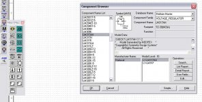
try "Misc/Vreg". mine starts with lm109h and ends with upc7924.
edit: this is how it shows on my screen. any other questions, Jonathan?
Attachments
Re: Of course it works
Hi Pedja,
I saw your circuit, and the only differences I saw between yours and the one that started this thread were:
And thanks for the sim.")
Tarun
Hi Pedja,
Pedja said:Here is how.
I saw your circuit, and the only differences I saw between yours and the one that started this thread were:
- The original value of R3 (220Ohm) has become 120Ohm in your circuit. Any ideas whether this has any important effect on performance?
- The addition of a 1uF cap. Should I add this cap to my circuit, across the R1-R7 combo? Any ideas of the appropriate value for this cap? Should this be something big (like 47-100uF) bypassed with something small (like a 100pF ceramic cap)?
And thanks for the sim.
Tarun
Thanks for the sim! This is great!
One question: should I add a cap from the ADJ terminal to ground? No such cap exists in the circuit I've drawn... I'd just faithfully replicated what Randy had shown in his book. I've asked this to Pedja too. When you put in the soft-start part into your sim, did you retain this cap?
Tarun
Wow! This is great news. Down from 400uV to 25uV due to the "soft start" circuit, which seems to do much more now than just soft-start.millwood said:without Cadj: 4mvpp
with a 10uf Cadj: 0.4mvpp
the soft start circuit: 25uvpp
One question: should I add a cap from the ADJ terminal to ground? No such cap exists in the circuit I've drawn... I'd just faithfully replicated what Randy had shown in his book. I've asked this to Pedja too. When you put in the soft-start part into your sim, did you retain this cap?
Tarun
Re: Re: Shall I proceed to PCB this circuit, then?
Tarun
Well, I don't. I was just looking for a good regulated PSU circuit. I almost regret starting this thread, though I learned a lot about my circuit in the process.peranders said:I think the design is rather OK but why do you need soft start?
Yes, this cap addition is a doubt I still have to clear. I've asked about this already. What value do you suggest? And about the 4700uF cap, I am just keeping place for a 2cm diameter cylindrical can electrolytic cap. I can always fit a 470uF, 1000uF, later, depending on what I need. What value do you suggest? Randy's book said 4700uF at both input and output, and it did seem like more in the power-amp smoothing cap territory to me, but then Randy knows more than me.Maybe you should add a capacitor between ADJ and ground but this is dependant of your load. 4700 uF at the out is much, much more than you need.
Tarun
Tcpip,
That resistor’s value was not really much about quality, I just wanted to ensure enough load current to make the regulator work regardless if something is plugged on it or not. Minimum load current is typically 3.5mA, max 5mA for LM317, but for some reason this performance has less tight tolerance for LM338 (max 10mA), so I put once that value (Vref/Iload(min)) of 120R and forgot on it.
Bypass cap on the adj pin improves the power supply rejection, noise and the output impedance. Value of 1uF you see in the shown schematic also has strayed from the sims with LM338 (it does not influences the slow start). As I can read the National’s datasheet, with LM317 there is no reason to go with more than 10uF here. Somewhat lower value can be enough as well. (In the case of LM338 things are more interesting, there are reasons both for higher and lower value.)
The biggest difference in PSRR with and without soft start I could get in simulations, was no more than few dB and that only in relatively small range. In most cases there was not any difference in PSRR.
Pedja
millwood said:
Output ripple:
without Cadj: 4mvpp
with a 10uf Cadj: 0.4mvpp
the soft start circuit: 25uvpp
This is absolutely not what I had expected. I still think that a switched off slow start transistor would not improve output ripple performance as your simulation shows.
Millwood, are you sure that the final voltage of the regulator was reached at that moment (i.e. that the transistor is really cut off)?
Did you measure the same performance in reality?
Steven
I'll add a can, then
Thanks a lot.
Tarun
Got it. I'll go with whatever Randy had put, in that case. I guess it's not critical.Pedja said:That resistor’s value was not really much about quality, I just wanted to ensure enough load current to make the regulator work regardless if something is plugged on it or not.
I guess I'll make provision for a small can, which can then be a 4.7uF or 10uF electrolytic cap, depending on whatever I may decide later.Bypass cap on the adj pin improves the power supply rejection, noise and the output impedance.... with LM317 there is no reason to go with more than 10uF here.
In that case, I guess I'll just retain the soft-start circuit, at least in the PCB, since it does no harm. The only change I'll make now will be the addition of the cap, then.The biggest difference in PSRR with and without soft start I could get in simulations, was no more than few dB and that only in relatively small range. In most cases there was not any difference in PSRR.
Thanks a lot.
Tarun
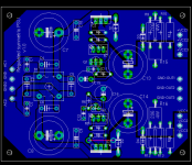
PCB with added caps
Luckily, I found the space to add the caps without too much re-placement. I've chosen 8.5mm diameter cans, I guess that should be big enough for upto 10uF. They are C15 and C16 in the layout. I've also added R15 and R16 power resistors for the quiescent load. These can be used instead of the sets of smaller 1W resistors, if you want. Since it's an either-or situation, I've placed the big ones over the smaller ones in the layout.
Luckily, I found the space to add the caps without too much re-placement. I've chosen 8.5mm diameter cans, I guess that should be big enough for upto 10uF. They are C15 and C16 in the layout. I've also added R15 and R16 power resistors for the quiescent load. These can be used instead of the sets of smaller 1W resistors, if you want. Since it's an either-or situation, I've placed the big ones over the smaller ones in the layout.
Attachments
Millwood:
Your version sure looks different from what I have. I don't even _get_ a "Component Browser". All that I have is a panel that says "Select a Component". And in the MISC subpanel, I see Buck Converter, Boost Converter, Buck/Boost Converter, and various ty0pes of transmission lines. No "Vreg".
Don't see anything that says, for instance, LM317H. Using the Search function didn't turn up anything, either.
The version that I have is Multisim 7 SP1b Demo.
I normally use Multisim only for fast and crude simulations, so it isn't such a big deal. But because it is such a phenomenally easy program to use, it would have been nice to get some more mileage out of it. Oh, well.
regards, jonathan carr
Steven said:Millwood, are you sure that the final voltage of the regulator was reached at that moment (i.e. that the transistor is really cut off)?
Did you measure the same performance in reality?
Steven
yes. I first selected DC (on multisim) and the output line was dead flat. to see the ripple, I had to select AC (which essentially filtered out the DC componenet) and lower the sensitivity until I see the ripple.
No. I didn't measure the performance in reality as I don't have any sophisticated measurement equipment.
Re: Thanks for the sim! This is great!
Tarun: I didn't use such a cap. I think the soft-start circuit also works like a cap multiplier but I need to think it through.
mine is from a few years ago so the might have changed it since. But the basic interface is similar to the EWB days. You may also simulate it from protel: it has lm317. But I haven't tried.
tcpip said:One question: should I add a cap from the ADJ terminal to ground? No such cap exists in the circuit I've drawn...
Tarun
Tarun: I didn't use such a cap. I think the soft-start circuit also works like a cap multiplier but I need to think it through.
jcarr said:Your version sure looks different from what I have.
regards, jonathan carr
mine is from a few years ago so the might have changed it since. But the basic interface is similar to the EWB days. You may also simulate it from protel: it has lm317. But I haven't tried.
Re: Thanks for the sim! This is great!
and it is "incorrectly implemented", as Fred put it. Think what performance you could have gotten out of it had the guys at National got it right,
On Steven's question, I didn't look at the steady state to see to what extent the transistor is conducting (i tend to agree with you there). I will poke around more tonight.
I will also put Fred's design against the "incorrectly implemented" National circuit and see how his circuit fares.
I think there are a couple of people with multisim maybe they can also simulate to see if I got the numbers wrong.
tcpip said:Wow! This is great news. Down from 400uV to 25uV due to the "soft start" circuit, which seems to do much more now than just soft-start.
Tarun
and it is "incorrectly implemented", as Fred put it. Think what performance you could have gotten out of it had the guys at National got it right,
On Steven's question, I didn't look at the steady state to see to what extent the transistor is conducting (i tend to agree with you there). I will poke around more tonight.
I will also put Fred's design against the "incorrectly implemented" National circuit and see how his circuit fares.
I think there are a couple of people with multisim maybe they can also simulate to see if I got the numbers wrong.
I didn't measure the performance in reality as I don't have any sophisticated measurement equipment.
Millwood, I don't think that it wouldn't take particularly fancy test equipment to throw something together on the bench and see if the sim of the soft-start/non-soft-start circuit is borne out in reality. A scope, a signal generator, and a small low-noise amp would do.
SY said:A scope, a signal generator, and a small low-noise amp would do.
that's pretty fancy to me,
anyway to do it with a DMM?
Don't believe everything you read......
The numbers for power supply rejection given for the Spice model look reasonable for the unbypassed and 10uF bypassed resistor to ground
look fairly reasonable with a rejection of 54dB and 74dB which are within a couple of dB of the model I used. However the 25uV would be a PSRR of 98 dB! I would love to have a three terminal regulator circuit with one extra transistor that did that........
I ran Spice models with and with out the circuit and saw no substantial difference much less a 160 times improvment. Lookind at DC values show there is no current through the transistor and it is not going to act like an emitter follower with no bias.
I would suggest posting the text models for regulator and transistor model and the Spice file as well.
For My Spice program:
C:\spice8\Circuits\Examples\Adjfollower.cir Setup1
*#save @R5 @R5[p] @V1 @V1[p] @R6 @R6[p] @R7 @R7[p]
*#save @C3 V(4) V(1) @R1 @R1[p] V(3) V(2) @C1
*#save V(5) V(6) @R2 @R2[p] @R3 @R3[p] @C2 @R8
*#save @R8[p] @Q1[icc] @Q1[p] @C4
*#alias vy2 v(5)
*#view ac vy2
*#view ac ph_vy2 = phase(vy2)
*#alias vy1 v(3)
*#view ac vy1
*#view ac ph_vy1 = phase(vy1)
.AC DEC 20 10 10000
*#op
.PRINT AC Vdb(VY2) phase(VY2)
.PRINT AC Vdb(VY1) phase(VY1)
X1 4 1 3 LM317TI { }
.SUBCKT LM317TI 1 2 3
*Connections Input Adj. Output
*LM317 voltage regulator - Texas Instruments
J1 1 3 4 JN
Q2 5 5 6 QPL .1
Q3 5 8 9 QNL .2
Q4 8 5 7 QPL .1
Q5 81 8 3 QNL .2
Q6 3 81 10 QPL .2
Q7 12 81 13 QNL .2
Q8 10 5 11 QPL .2
Q9 14 12 10 QPL .2
Q10 16 5 17 QPL .2
Q11 16 14 15 QNL .2
Q12 3 20 16 QPL .2
Q13 1 19 20 QNL .2
Q14 19 5 18 QPL .2
Q15 3 21 19 QPL .2
Q16 21 22 16 QPL .2
Q17 21 3 24 QNL .2
Q18 22 22 16 QPL .2
Q19 22 3 241 QNL 2
Q20 3 25 16 QPL .2
Q21 25 26 3 QNL .2
Q22A 35 35 1 QPL 2
Q22B 16 35 1 QPL 2
Q23 35 16 30 QNL 2
Q24A 27 40 29 QNL .2
Q24B 27 40 28 QNL .2
Q25 1 31 41 QNL 5
Q26 1 41 32 QNL 50
D1 3 4 DZ
D2 33 1 DZ
D3 29 34 DZ
R1 1 6 310
R2 1 7 310
R3 1 11 190
R4 1 17 82
R5 1 18 5.6K
R6 4 8 100K
R7 8 81 130
R8 10 12 12.4K
R9 9 3 180
R10 13 3 4.1K
R11 14 3 5.8K
R12 15 3 72
R13 20 3 5.1K
R14 2 24 12K
R15 24 241 2.4K
R16 16 25 6.7K
R17 16 40 12K
R18 30 41 130
R19 16 31 370
R20 26 27 13K
R21 27 40 400
R22 3 41 160
R23 33 34 18K
R24 28 29 160
R25 28 32 3
R26 32 3 .1
C1 21 3 30PF
C2 21 2 30PF
C3 25 26 5PF
CBS1 5 3 2PF
CBS2 35 3 1PF
CBS3 22 3 1PF
.MODEL JN NJF(BETA=1E-4 VTO=-7)
.MODEL DZ D(BV=6.3)
.MODEL QNL NPN(EG=1.22 BF=80 RB=100 CCS=1.5PF TF=.3NS TR=6NS CJE=2PF
+ CJC=1PF VAF=100)
.MODEL QPL PNP(BF=40 RB=20 TF=.6NS TR=10NS CJE=1.5PF CJC=1PF VAF=50)
.ENDS
C1 2 0 4.7uF
Q1 0 2 1 BC557
.MODEL BC557 PNP BF=325 BR=4 CJC=12.5P CJE=20.8P IKF=.3
+ IKR=.45 IS=50.7F ISE=15.6P NE=2 NF=1 NR=1 RB=3.63 RC=.363
+ RE=.907 TF=611P TR=138N VAF=120 VAR=24 XTB=1.5
R2 6 5 220
R3 5 0 1K
C2 5 0 10uF
X2 4 6 5 LM317TI { }
R8 6 0 2.4K
R1 1 0 2.4K
R5 1 3 220
V1 4 0 DC=30V AC=1V
C4 4 0 0.1uF
R6 3 0 1K
R7 3 2 47K
C3 3 0 10uF
.END
GUI screen below:
Attachments
Fred, now that you are on the simulation bandwagon, have you tried to simulate
1) if the National circuit will do soft start?
2) if Cadj will improve ripple rejection?
Hopefully, your simulator will tell you how wrongly implemented that National circuit is.
But before you do all that, please make absolutely sure that you are simulating the National circuit, not your truly incorrectly implemented one. Pleeeeeeeeeese!
and i can spot it, experts like you should have done so light years ago.
Well, since I also have great difficulties to see how the original
circuit, in the first post in this thread, could improve regulation
I also did a quick Spice experimetn earlier tonight. It wasn't
very rigourous and I used the LM317 model I happen to have,
but since now even Fred posted Spice results I could perhaps
do that as well without getting a rebuke for it, especially since
they agree with Freds results.
First, I should note that I mainly looked at load regulation rather
than line regulation, using a resistive load in parallel with a square
wave current sink. I found no mentionable difference between
the BJT version and the ordinary resistive divider version. Looking
at the Ie of the BJT it was on the order of picoAmperes, which seems
pretty consistent with the argument that it should not be conductiong
at all in steady state.
Sloan circuit Spice output plot
This is not a hard circuit to measure either A simple mosfet follower with a 40V supply and a resistive divider to get 30 volts DC on the output for the input signal with a signal generator capacitor coupled to get 1 volt AC will work fine. An op amp with a gain of one thousand (60dB) should show the output voltage fine. Use AC coupling on the op amp input selected for a lower corner frequency than the frequency under measurement. You should even be able to get the parts at Radio Shack.
Willingness to trust very questionable Spice results over a measurement this easy to make is just laziness or intellectual dishonesty about the question of wanting to know if this circuit works to improve the performance of the regulator. It is ashamed that certain people can't get over this hump (maybe ripple actually) to get on to discussing circuits that will actually work to achieve this design goal. It is unfortunate that self interest and ego are so much more important than helping those on the forum interested in correct information. It isn't the first time or will it be the last that this has happened........
The output of my simulation below:
Attachments
- Status
- This old topic is closed. If you want to reopen this topic, contact a moderator using the "Report Post" button.
- Home
- Amplifiers
- Solid State
- LM317-based regulated PSU: how does this thing work?