A few days ago I got my hands on a Technics SU-V65A amplifier (Class AA, VC-4 Amplifier System, etc). As with a lot of Technics amps with SVI/RSN ICs, this one also had a dead SVI4004 IC.
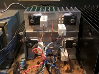
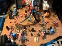
Long story short, I`ve substituted it with 2 pairs of TIP35/36C transistors with some lite circuit modding. It looks a bit messy, but I dit it in a few ours. The end result looks good, sounds good, I have no idea of THD figures as I don`t own an osciloscope.
Here are a couple of pictures, if someone is interested to do this themselves, reply on this thread.
Attachments
You may be aware of the limited Vceo of TIP35/36 transistors and the high rail voltages used in most Technics SUV series amplifiers. In the SUV65, they are nominal +/- 53V probably too high for safety with TIP35/36.
As the SV14004 module is 24 pins and contains a lot more circuitry than just the output transistors, I'm wondering how much of the amplifier could be left after the necessary changes allow simple (presumably class AB) pairs to substitute for the power module. A schematic or at least a block diagram would be informative and allow others to understand what you did because it is not a simple design that lends itself to modification. Like the Quad designs, it is a current dumper, with feed-forward stabilization derived from a bridge network in the SV14004/3 modules.
Link to the original schematic - a poor one but there are not many options: TECHNICS SU-V65A SCH Service Manual free download, schematics, eeprom, repair info for electronics
Last edited:
You may be aware of the limited Vceo of TIP35/36 transistors
The TIP35C/36C has a Vceo of 100V the B has 80V and the a has 60. I`ve bypassed the SVI4004 circuit and used only the class "AA" circuit. In short, I replaced the 2SC/2SA final transistors in the circuit with the TIPs and biased it to 20mV. I did it as an experiment and out of curiosity, honestly I didn`t think that it would work.
Certainly, it must have been pleasing to have the amplifier working but for how long? From your description, you drive the TIP35/36 pair with the voltage stage output from a 2SC2631/2SA1129 complementary pair? These voltage drivers are only rated for peak currents of 100mA. I'm sure it works just as you say at low output levels, but for how long and up to how much output current?
You need either darlington output transistors, a current buffer stage or to add driver transistors with at least 1.5 amp current rating to drive the output stage up to decent power levels. TIP35/36 have good current gain for general purpose devices but not as good as many high quality audio types and even these use a driver stage with larger, TO220 type driver transistors.
Regarding voltage rating of TIP35/36....
100V is a maximum (negligible current) rating for C types, not the rating at maximum current. Look at the SOA graph, fig.6 here: http://www.onsemi.com/pub_link/Collateral/TIP35A-D.PDF. The transistor has the same SOA characteristic for either A,B,C types so it does not produce more power just because it can withstand higher C-E voltage. The current rating at a voltage of 100V is only around 100 mA and both transistors will be exposed to at least 90V here.
Certainly, it must have been pleasing to have the amplifier working but for how long?
Yes, I know that those drivers are not powerfull enough, I will swap them with the two 2SC3944/2SA1535. These were the main transistor in the class AA circuit. Will they do the job?
I already ordered two pairs of 2SC5200/2SA1943 to change the TIP35C/36Cs. I was just curious if it can be done and I already had these on hand. For the moment I don`t use the amplifier anyway.
I wanted to leave the class AA circuit untouched and darlington the power transistors with the 2SC3944/2SA1535, but the emitter voltage was not enough to drive another pair in darlington. The 2SC3944/2SA1535 were getting 0.6V at the base and I didn`t know what to modify to get 1.2V so I could ad another emitter follower.
Maybe you could tell me
 . My electronics knowledge is very limited. I`ve found a Marantz PM72 service manual which uses the same AN7062N voltage amplifier, and that amp has 3 emitter followers, and the first transistor has 1.7V at the base.
Any help is appreciated. Thanks!
The PM72 circuit obviously works well but it is complicated and I think it may be difficult to stabilize. Bob Cordell has written an excellent text, specializing in such EF triple designs, which is available via Amazon and other booksellers. Read that before trying triples out.
For inexperienced DIYs, I don't suggest them. Start with the following article by Rod Elliott which should show you how the output stage is built on the VAS and shows mainly simple EF or CFP output stages which will be all you need. It should also be a great learning aid to simulate the design for yourself before building anything.
Of course, there is also a lot more info. on the site - enough to keep any DIY busy for years
Elliott Sound Products - Audio Power Amplifier Design Guidelines
- Status
- This old topic is closed. If you want to reopen this topic, contact a moderator using the "Report Post" button.
- Home
- Amplifiers
- Solid State
- For people with Technics Class AA (SVI4004/4003) amplifiers