New thread, as this became increasingly Off Topic for the thread http://www.diyaudio.com/forums/showthread.php?s=&threadid=27907
OK, what graphs I am looking at for BJTs?
Always look at the SOA, as you don't want to destroy the device.
Provided, that this is not at the output stage (where you have to look at transient thermal resistance graph and into the catalog of your preferred heatsink supplier) and not a low level (phono, mic) stage (where you have to look at the noise figures graph), there are three essential graphs:
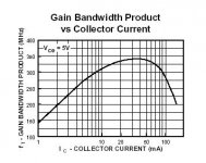
Transit frequency as a function of collector current:
Stay to the left of the peak.
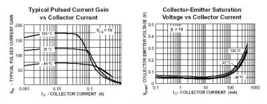
DC current gain as a function of collector current:
Stay to the left of the point where the hFE is 3dB below maximum.
Apply (if provided) the graph best matching your expected junction temperature and Vce
Collecter emitter saturaton voltage as a function of collector current:
Stay below the Ic, where VCEsat is about 200..300% the minimal VCEsat
(If there is no minimum, i.e. VCEsat drops ever more for lower Ic, a compareable point is 50% of the Ic where there is a "kink" in the double log plot).
These are only my cookbook recipes. And they only apply for DIY, where you haven't to worry so much about decive cost - as these rules will often imply using a more expensive BJT with a much higher "rated" Ic, if you are looking for a specific collector current.
Regards,
Peter Jacobi
lumanauw said:[...]About the original question, it is not about final stage only. But I mean is for all stages of audio power amplifier. The point is to understand about how a single transistor works, and then I can decide to design or choose the good operating point for every stage in audio power amp.
What is really the way to pick good operating point for a certain transistor? What graph should be looked at, in the datasheet there are many graph. [...]
OK, what graphs I am looking at for BJTs?
Always look at the SOA, as you don't want to destroy the device.
Provided, that this is not at the output stage (where you have to look at transient thermal resistance graph and into the catalog of your preferred heatsink supplier) and not a low level (phono, mic) stage (where you have to look at the noise figures graph), there are three essential graphs:
Transit frequency as a function of collector current:
Stay to the left of the peak.
DC current gain as a function of collector current:
Stay to the left of the point where the hFE is 3dB below maximum.
Apply (if provided) the graph best matching your expected junction temperature and Vce
Collecter emitter saturaton voltage as a function of collector current:
Stay below the Ic, where VCEsat is about 200..300% the minimal VCEsat
(If there is no minimum, i.e. VCEsat drops ever more for lower Ic, a compareable point is 50% of the Ic where there is a "kink" in the double log plot).
These are only my cookbook recipes. And they only apply for DIY, where you haven't to worry so much about decive cost - as these rules will often imply using a more expensive BJT with a much higher "rated" Ic, if you are looking for a specific collector current.
Regards,
Peter Jacobi
Hi,
Thanks, Pjacobi for the advice. Since I'm only an amateur I cannot digest all instantly. I will try to understand the whole answer.
I really wonder how you know so much about so many application of transistors outside audio. Since my introduction with transistor only in audio field, it opens my eyes about transistors in other fields.
This is the first examination. Mentor=Pjacobi ; student=Lumanauw ; Case=MPSA06
Ok, I always calculate the current X operating voltage, to get dissipation. But dont know how to determine the max current in SOA. Since in final stage audio power amp is very fluctuative, is it to determine max current in one final transistor. It is the VCC/load (example +/-32V/4ohm=8ampere)?Always look at the SOA, as you don't want to destroy the device.
The only frequency related graph from a transistor datasheet I can found is about bandwith. Is this the one? If this is the one, then when I use MPSA06, it should stay below 40mATransit frequency as a function of collector current:Stay to the left of the peak.
Attachments
In the HFE-Ic graph, the curve is quite flat. If we look for 3db below maximum it will be very small figure. How to solve this?DC current gain as a function of collector current:Stay to the left of the point where the hFE is 3dB below maximum.
Apply (if provided) the graph best matching your expected junction temperature and Vce
Also I cannot find any junction temperature graph.
The minimal Vcesat is about 0.07V, so the 300% is 0.21V. It will be 300mA? Off course I will use below this, from the first restriction it is only alowed for below 40mA.Collecter emitter saturaton voltage as a function of collector current:Stay below the Ic, where VCEsat is about 200..300% the minimal VCEsat
(If there is no minimum, i.e. VCEsat drops ever more for lower Ic, a compareable point is 50% of the Ic where there is a "kink" in the double log plot).
Pjacobi, this 3 graph semms to limit the current. Since audio is about AC current, I assume this is for Bias/ Standing current.
Since we have know the max current, is there any possible way to determine 1 operating point that is the best?
How about determining operating voltage (Vce)?
And is this method also works for mosfets? Or there is other method for mosfets?
Attachments
- Status
- This old topic is closed. If you want to reopen this topic, contact a moderator using the "Report Post" button.