I can't recall ever seeing a commercial mainstream AC coupled amp with dedicated additional circuitry to silently charge/discharge the coupling cap.
I would agree - although I have seen occasional 'anti-thump' circuits that use a relay, and wait a second before connecting the speaker. But I suspect those were an 'after thought' where the 'thump' was particularly bad.
If there is a protective circuit then this may provide a short across the speakers during turn on and turn off. If so, it may be faulty. That is where you should look. Find a circuit diagram.
Have you ever come across an example of this in a mainstream amp of the late 1960's........... and curiosity got the better of me, I dug the circuit out.
So, definitive answer. The thump is normal.
Attachments
I would agree - although I have seen occasional 'anti-thump' circuits that use a relay, and wait a second before connecting the speaker. But I suspect those were an 'after thought' where the 'thump' was particularly bad.
Yes, you could add a basic switch on delay circuit fairly easily, and rely on the slow rate of collapse of the rails to cover the time period of the relay dropping out on power off.
----------------------------------------------------------------------------------------
To charge a speaker coupling cap fully via a simple resistor (say 100 ohm) takes quite a long time to get a silent switch on. Perhaps 10 to 15 seconds for a good subjective result. Making the resistor lower starts to give rise to dissipation issues and extra loading of the amp. I would have thought applying a short wasn't a great idea, particularly knowing how easily semiconductors of that era could curl up their toes.
500R with 1000uF will have a time constant of 0.5s. The cap will be substantially charged within about 2 seconds - provided the relay works. If not, everything happens more quickly through the speaker. There is an exponential decay of the 'DC' so it never actually reaches zero but gets close enough within a reasonable time. Doubling the cap will double the trouble.
Coupling caps
Hello thanks for the advice on the diodes, put them in and the new smoothing caps the tranny is not getting hot and is quite. Changed the two 10uf 100v RC snubber caps and got the Dc offset down to +/- 20mv. When you turn the amp on/off their is no thump at all but the DC is still their. I'm now in two minds to put the new coupling caps in as they are twice the value of the old ones. Would it be better to put like for like or will the new caps do as I have already got them and they are a perfect fit. thanks
Hello thanks for the advice on the diodes, put them in and the new smoothing caps the tranny is not getting hot and is quite. Changed the two 10uf 100v RC snubber caps and got the Dc offset down to +/- 20mv. When you turn the amp on/off their is no thump at all but the DC is still their. I'm now in two minds to put the new coupling caps in as they are twice the value of the old ones. Would it be better to put like for like or will the new caps do as I have already got them and they are a perfect fit. thanks
Changing the speaker coupling caps will do harm, even at double the capacitance value. DC offset ? That only applies to amplifiers using 'split' or 'dual' power supplies (a positive and a negative rail).
Your 'DC offset' will always be zero across the speaker itself although many DVM's may not give an absolutely steady 0.0000 volt reading for various reasons. But the offset is zero. Honest")
In an amp of this age, all the electrolytics are suspect simply because they are 'wet' chemical devices and so over the years will have deteriorated and lost some of their value and 'goodness' (or more specifically developed a high E.S.R. or equivalent series resistance)
Your 'DC offset' will always be zero across the speaker itself although many DVM's may not give an absolutely steady 0.0000 volt reading for various reasons. But the offset is zero. Honest
In an amp of this age, all the electrolytics are suspect simply because they are 'wet' chemical devices and so over the years will have deteriorated and lost some of their value and 'goodness' (or more specifically developed a high E.S.R. or equivalent series resistance)
Would it be better to put like for like or will the new caps do as I have already got them
and they are a perfect fit. thanks
Since the existing output caps are 2x500uF, and the new ones are 1000uF,
you can just install one of the 1000uF and leave the other footprint empty,
which keeps the value the same.
Changing the speaker coupling caps will do harm, even at double the capacitance value.
Funny how you can read and re-read something to make sure its correct and then spot an error later.
Should have read, 'Changing the speaker coupling caps will do no harm'.
On an amp like this I think you will always see some 'voltage' across the speaker if you measure with a DVM simply because the amp output isn't truly 'steady'.
OK, that's hard to explain... the amp output will reflect tiny changes in mains voltage as the rails constantly shift and change. That is because the DC conditions in the amp constantly change in response to this, and that change will show as a slight variance in the voltage across the speaker. You also need to remove any HF noise for a DVM to read true. That means connecting the DVM via a simple low pass filter consisting of a resistor and cap.
Ultimately, if you read any small DC voltage across the speaker with the new caps fitted then what you are seeing is a measurement artefact and not a real problem.
Coupling caps
Hello Thanks for your help with my amp. I fitted the coupling caps today and put the amp on my HIFI it sounds very good its a very old amp but does not sound old. I know their is still a lot to do to make it sound as good as it can. Apart from recapping what would be the best thing to do, I have priced up all the transistors and that would cost £140 from little diode. Would that be a bad idea or will other things make a bigger difference. Also I have a service manual but their is no mention on setting the bias what would be the value and where are the test points. Thanks
Hello Thanks for your help with my amp. I fitted the coupling caps today and put the amp on my HIFI it sounds very good its a very old amp but does not sound old. I know their is still a lot to do to make it sound as good as it can. Apart from recapping what would be the best thing to do, I have priced up all the transistors and that would cost £140 from little diode. Would that be a bad idea or will other things make a bigger difference. Also I have a service manual but their is no mention on setting the bias what would be the value and where are the test points. Thanks
Replacing the transistors just for the sake of it = very very bad idea. Older designs such as this can rely heavily on the device characteristics, far more so than modern designs. That means potential problems in the form of stability issues and not being able to set the bias. Modern parts may be nominally similar but made using different production processes. For example a 2N3055 of the late 60's (werethey around then) or the early 70's is nothing like a 2N3055 produced today.
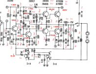
Who mentioned bias... this appears to be a fixed bias design. The components connected in series with that diode in the middle of the power amp set the bias. The resistor with an oval around it is actually a thermistor, used to keep the bias constant as temperature changes. The lower emitter resistor in the output transistor pair has what looks like a test point attached on the circuit diagram. The voltage across that resistor is used to deduce the bias current (ohms law) but what the recommended bias is would be any ones guess. Its almost certainly under biased from what would be considered the optimal for this design but that is done to ensure reliability and freedom from thermal runaway.
Who mentioned bias... this appears to be a fixed bias design. The components connected in series with that diode in the middle of the power amp set the bias. The resistor with an oval around it is actually a thermistor, used to keep the bias constant as temperature changes. The lower emitter resistor in the output transistor pair has what looks like a test point attached on the circuit diagram. The voltage across that resistor is used to deduce the bias current (ohms law) but what the recommended bias is would be any ones guess. Its almost certainly under biased from what would be considered the optimal for this design but that is done to ensure reliability and freedom from thermal runaway.
The main transistors are B-17008, in the service manual its you can also use 2SD118 which are £15 each from little diode so I will not fix what's not broke. I can tell at the moment that the bias is not too high because I had it on loud for about two hours and it barely got warm and it sounded great. I have herd that with some of these old Luxmans that as long as its not over say 250MA across the emitter resistor it will be ok is that a good ballpark figure. I cannot yet work out for myself what the correct value should be, until 4 months ago I did not know a capacitor was.
You're doing well
This amplifier uses what is known as a 'Quasi Complementary' output stage which means it uses two devices of the same polarity (two NPN's). A typical bias current could be around the 50ma region which would give a voltage of around 50mv across either of the 1 ohm emitter resistors. That in turn would give a power dissipation of 80 (rail voltage) times the current (0.05) which is 4 watts in total or 2 watts per device. Its 2 watts per device because each will have nominally half the supply voltage across its collector and emitter.
In practice, any current from a couple of milliamps upward will remove audible distortion although only one specific current will give optimum minimum distortion.
- Status
- This old topic is closed. If you want to reopen this topic, contact a moderator using the "Report Post" button.
- Home
- Amplifiers
- Solid State
- Will increaseing coupling caps cause problems