Hi,
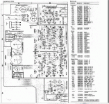
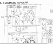
The right channel of this amp has blown. I replaced the 2 power transistors on this channel and six other small transistors , Q5,Q6 and Q7, three transistors on each channel. These transistors are also mounted on the heat sink. The amp is working alright. Now, what is not normal is this- according to the service manual, the bias voltage (taken across the 2 emitter resistors should be adjusted to 3mV DC. I am not able to get this voltage. When I turn the bias resistor fully anticlockwise, it reads below 1mV and when turned fully clockwise, it reads only about 2.8mV. This amp when I fixed it the last time, I manage to set the bias to 3mV, but the bias gradually increases according to time. That was the reason why I decided to change the six small transistors, Q5,Q6 and Q7 mounted on the heat sink. I have set the bias trimmer for both channels halfway and both read around 1mV. Would setting the bias below the recommended 3mV cause any problem to the amp. Please advice.
Thanks
Carlos
I am unable to upload the service manual, as it is more than 7MB.
Did you use the correct transistors? Are the double diodes OK?
I am using higher power transistors, 2SC4029 and 2SA1553. They work OK.
this amplifier is a nightmare to stabilize ..and as far as i understand the bias transistor is located together with the limiter transistors in the wrong place of the already small heat sink
Changing outputs to others than the original will produce a number of issues since this amplifier is depending on hfe but also the thermal behavior of the scheme Vbe multiplier /Vi limiter
Kind regards
Sakis
Changing outputs to others than the original will produce a number of issues since this amplifier is depending on hfe but also the thermal behavior of the scheme Vbe multiplier /Vi limiter
Kind regards
Sakis
this amplifier is a nightmare to stabilize ..and as far as i understand the bias transistor is located together with the limiter transistors in the wrong place of the already small heat sink
Changing outputs to others than the original will produce a number of issues since this amplifier is depending on hfe but also the thermal behavior of the scheme Vbe multiplier /Vi limiter
Kind regards
Sakis
Thanks, Sakis. This amp keeps blowing every now and then. Is there anything that can be done to help.
Carlos
Been repairing a few of those had the chance to use strictly original parts even considering the grade of transistors and worked pnp .
Though the all circuit as far as i understand is implemented wrong
You could convert the all thing to a normal amplifier with a classic topology rather than experimental one but this will be too much trouble for a worthless amplifier .
I think that what is causing the trouble is the way the protection circuit works so i could remove it totally hardwire a classic vbe multiplier to work with the amplifier and calculate a simple VI limiter around it only if necessary to the user
the rest of the amp is very pretty str8 4ward so i dont find a reason for why not ?
Kind regards
Sakis
Been repairing a few of those had the chance to use strictly original parts even considering the grade of transistors and worked pnp .
Though the all circuit as far as i understand is implemented wrong
You could convert the all thing to a normal amplifier with a classic topology rather than experimental one but this will be too much trouble for a worthless amplifier .
I think that what is causing the trouble is the way the protection circuit works so i could remove it totally hardwire a classic vbe multiplier to work with the amplifier and calculate a simple VI limiter around it only if necessary to the user
the rest of the amp is very pretty str8 4ward so i dont find a reason for why not ?
Kind regards
Sakis
Thanks Sakis, for your straight forward and honest opinion . I feel the same as after so many attempts, the amp still fails.
Kind Rgds
Carlos
I expect that the concept of this circuit is that Vi limiter will shunt bias and drive while sharing similar temperature with the outputs a characteristic that should have a target like : Vi limiter behaves different if cold and different if toasted together with the outputs.
I expect that the idea is fine has a good target but as said the implementation is bad .
if you have a circuit that is so much depending on temperature then obviously you don't implement it in the middle of the very small heatsink anyway while locating theVbe multipliers the one next to each other ( i mean for left and right )
My gut says though that if you remove the protection circuit the amplifier will power up but then you will need to hardwire the Vbe multiplier ( jumper between C-E of transistors , remove diodes and capacitors to ground, remove diodes that sense form output transistors ... )
Kind regards
Sakis
Last edited:
Revised Manual?
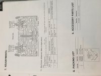
Hi just came across this post about getting the Bias set on the Sansui B-77. The service manual I've got has the instructions of connecting the meter between the emitters of transistors kQ10,kQ11 and adjusting for 3mv. The B-55 (the little brother) calls for the same procedure. I would assume the procedure for using the resistor as the test point came later, and probably is a safer bet than the possibility of test leads accidentally shorting between the legs of the transistor. (The things you learn as a novice ) Looking at my service manual I believe the bias test point is kR25? Can someone with the later manual verify this is the right test point?
Thanks!
Alex
Hi just came across this post about getting the Bias set on the Sansui B-77. The service manual I've got has the instructions of connecting the meter between the emitters of transistors kQ10,kQ11 and adjusting for 3mv. The B-55 (the little brother) calls for the same procedure. I would assume the procedure for using the resistor as the test point came later, and probably is a safer bet than the possibility of test leads accidentally shorting between the legs of the transistor. (The things you learn as a novice
Thanks!
Alex
Attachments
- Status
- This old topic is closed. If you want to reopen this topic, contact a moderator using the "Report Post" button.
- Home
- Amplifiers
- Solid State
- Sansui B77


