Hi to all
I'm building 2 Class ab amps for my 4 ohms Subwoofers and the power of each one is between 400 to 500W
the question here is how to match output mosfets so that they share the current equally, because they're not sharing at all and some of them gets really hot while some works cool

Other than output mosfet thermal problem everything is good and output sound is great
Could quiescent current on mosfets effect this unbalanced sharing?
I appreciate any help
I'm building 2 Class ab amps for my 4 ohms Subwoofers and the power of each one is between 400 to 500W
the question here is how to match output mosfets so that they share the current equally, because they're not sharing at all and some of them gets really hot while some works cool
Other than output mosfet thermal problem everything is good and output sound is great
Could quiescent current on mosfets effect this unbalanced sharing?
I appreciate any help
If they are as unbalanced as you say then I'd be a little concerned over the actual devices tbh. Devices bought from a recognised supplier and from the same batch should be reasonably close. Have you also confirmed the amp is stable ?
Nelson Pass has some articles over at Passdiy,
https://www.passdiy.com/project/articles/matching-devices
Hope Q3 and Q6 are not as drawn")
Nelson Pass has some articles over at Passdiy,
https://www.passdiy.com/project/articles/matching-devices
Hope Q3 and Q6 are not as drawn
I have found that the spread of Vgs from same batch and random mosFETs is so wide that parallel pairs (or more) cannot share current equally unless one is very lucky.
One must measure Vgs at the intended operating current. Select close matching Vgs sets for paralleled operation.
Even selected sets will still run at different Id and here we have to resort to using at least some source resistance to help reduce the current imbalance.
There is a problem.
Temperature during testing.
One must control the temperature such that Tj is the same for all the devices one is trying to measure/select.
Reducing Vds to around 1V to 2V helps reduce the deltaT, but one must adopt a methodology that gives some semblance of controlling Tj.
But that low Vds does not mimic the actual operating conditions in the amplifier. That leads to some error that only becomes evident after the assembly is complete.
Oh, and match the source resistors as accurately as you need to get Id result from their Vdrop. I aim for <0.5% range in a group (that is not the same as +-0.5%, which is a range of 1%)
Last edited:
Hi Guys
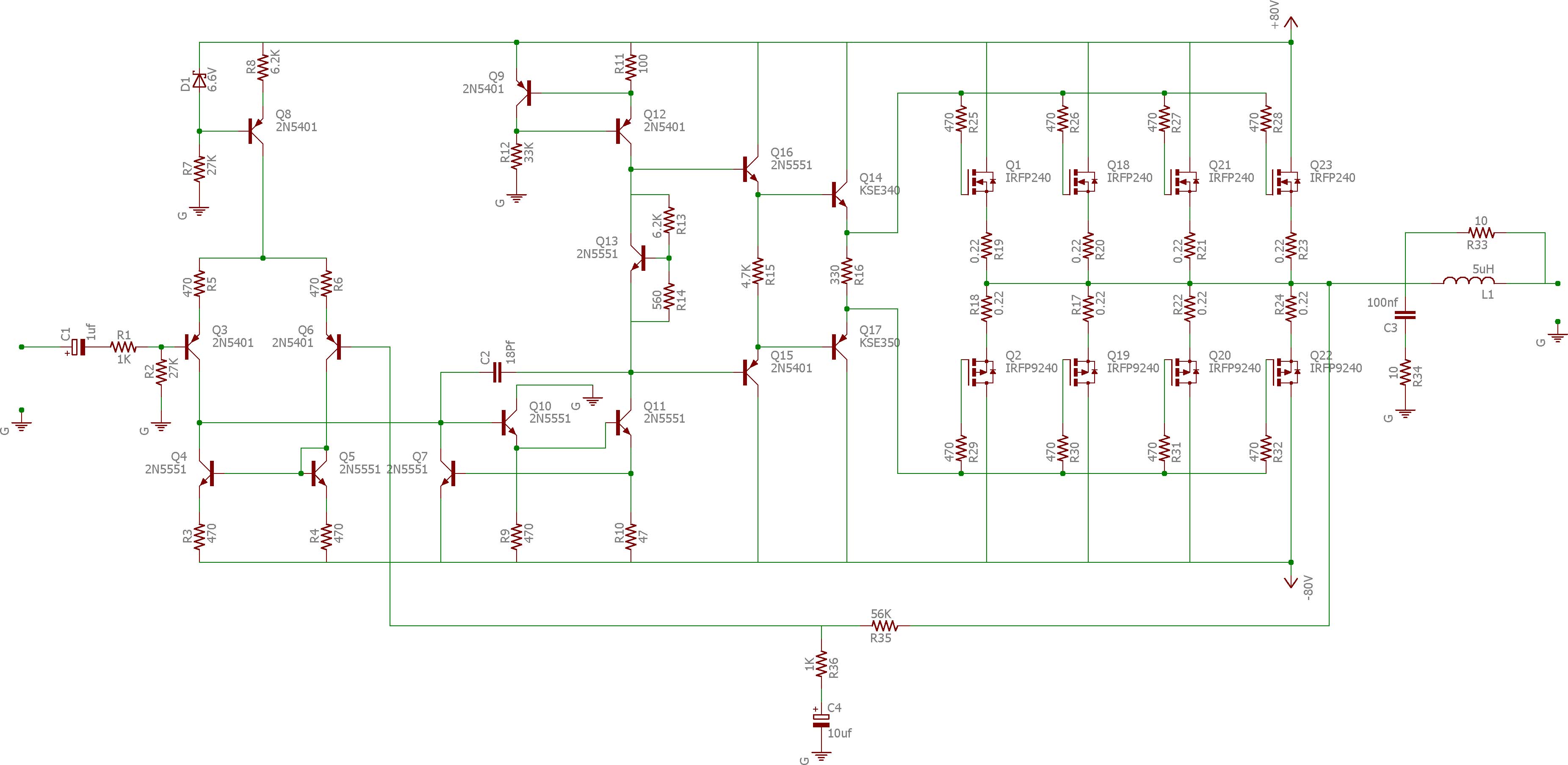
The circuit cannot work as drawn since the input devices are upside down.
There will be no bass response either since the feedback cap is listed as 10uF - should be 10mF at least. (m=milli).
As a subwoofer-only amp, you can get away with under-biasing the output devices to have a cooler idle condition. However, damping, THD and overall performance is always better with correct biasing.
There sahould be a DC pathg to ground from the output node. a 1k is fine but should be a 1W for the rails listed. This helps to keep DC offset low and improve settling. DC offset will be further improved if the base-leak at the input is made equal in value to the series feedback resistor.In a fullrange amp both Rs would be much lower, say 10k with corresponding reduction of the shunt feedback R and increase in shunt feedback C.
The miller compensation cap should be a bit higher to avoid oscillation.
have you simulated this amp?
The schemo looks like an Eagle drawing but many of the connections are missing (dots where there should be a connection). So, if it is a PCB program, there may not be a good board result.
Have fun
Hi,
10uF is about -3dB @ 15Hz, 10,000uF = 10mF is a stupid value.
rgds, sreten.
Better device matching and increased current sensing resistors.
0.22R is very low for FETs, but would be fine with BJT's. BJT's
would also swing nearer the rails, giving more power output.
10uF is about -3dB @ 15Hz, 10,000uF = 10mF is a stupid value.
rgds, sreten.
Better device matching and increased current sensing resistors.
0.22R is very low for FETs, but would be fine with BJT's. BJT's
would also swing nearer the rails, giving more power output.
Last edited:
Hi Guys
16Hz is the -3dB point for the values in your circuit, but the gain is not flat until 160Hz. Worse than that is the THD penalty. See Self's APAD or Cordell, who both agree on these points and that this is not the place in the circuit where low-frequency response should be defined.
To eliminate the THD influence of the feedback cap, the related -3dB frequency must be a fraction of 1hz. Obviously, this is only of concern to those who desire truly low THD.
The circuit won't work as drawn anyway.
Have fun
Hi Guys
With respect to matching the mosfets:
The usual method is to match gm, which is high for the devices specified but quite variable. It is easy to measure Vgs at the proposed idel current and then assume that gm is similarly matched, but as Andrew has pointed out the dynamic matching will be questionable.
Pass and Thagard took the only workable approach and made the source resistors much higher in value and used many devices in parallel. Their example was a 100W amp with twelve pairs of outputs and Rs=1R.
The front-end circuit should be decoupled from the output stage and preferably be of higher value if you want to extract all the power you can from the main rails. However, this pushes the drivers to handle even higher charge-discharge currents for the mosfet capacitances. It is always beneficial to have supply rails higher than the rated power requires.
Have fun
I use tons of IRF250/240/450 in my Musical Instrument and PA amps, which are *regularly* abused and run under grueling conditions anyway.
Never ever had a MosFet matching problem, always buy straight from the distributor by the closed box or at least by the stick(s), so all come from the same batch anyway, but to play it safer I still test them with this, which matches them at 11mA current, a value which will later be used for biasing, so it's as realistic as can be:
Hope it helps.
EDIT: in the OP's amp, I'd check wiring carefully, make sure that gate resistors are as close to MOS pins as possible (I twist and solder them straight to pins, go figure) , the overheating ones might be unstable and sporadically oscillating.
Never ever had a MosFet matching problem, always buy straight from the distributor by the closed box or at least by the stick(s), so all come from the same batch anyway, but to play it safer I still test them with this, which matches them at 11mA current, a value which will later be used for biasing, so it's as realistic as can be:
An externally hosted image should be here but it was not working when we last tested it.
Hope it helps.
EDIT: in the OP's amp, I'd check wiring carefully, make sure that gate resistors are as close to MOS pins as possible (I twist and solder them straight to pins, go figure) , the overheating ones might be unstable and sporadically oscillating.
Thank you, I'll do thatThere sahould be a DC pathg to ground from the output node
No I haven'thave you simulated this amp?
But this schematic is from "Bob Cordell" book with a few changes
Yes, it is eagleThe schemo looks like an Eagle drawing but many of the connections are missing (dots where there should be a connection). So, if it is a PCB program, there may not be a good board result.
but I just used it to draw my schematic to show here and for PCB I know I have to do some work
Hi Guys
16Hz is the -3dB point for the values in your circuit, but the gain is not flat until 160Hz. Worse than that is the THD penalty. See Self's APAD or Cordell, who both agree on these points and that this is not the place in the circuit where low-frequency response should be defined.
To eliminate the THD influence of the feedback cap, the related -3dB frequency must be a fraction of 1hz. Obviously, this is only of concern to those who desire truly low THD.
Have fun
Hi,
Generally very trivial issues for a subwoofer,
and at least 10,000uF is utter nonsense.
rgds, sreten.
Last edited:
0.22R is very low for FETs, but would be fine with BJT's. BJT's
would also swing nearer the rails, giving more power output.
The reason that I'm using FETs instead of BJTs is that I couldn't find any high voltage power bjt in my city
and also Fets are much easier to drive and much robust I think
What value do you propose for Sourse resistors?
I figured it out
the problem was that some of the mosfets were fake
I just have 2 original of each type so I lower the supply rails to test it out
Now mosfets with about 140W in the output (4 ohms) share the current near each other(only two pairs installed)
is 150mA quiescent current good for each mosfets??? and also how many output pairs do you recommend to withstand 400W RMS for a 4 ohms load (worse case scenario)
So you think installing a cap that huge with enormous leakage current (comparing to 10-100uF cap) would help?Hi Guys
"utter nonsense."
We know where you stand with respect to getting low THD... and to "respect".
Have fun
Hi to all
I'm building 2 Class ab amps for my 4 ohms Subwoofers and the power of each one is between 400 to 500W
the question here is how to match output mosfets so that they share the current equally, because they're not sharing at all and some of them gets really hot while some works cool
Why are you driving those IRFP's with an EF 3 ??
You just need to overcome Ciss. No I to drive here ??
OS
Why are you driving those IRFP's with an EF 3 ??
You just need to overcome Ciss. No I to drive here ??
OS
this design is used for driving power BJTs and yes we can eliminate the first EF drive stage with no harm
- Status
- This old topic is closed. If you want to reopen this topic, contact a moderator using the "Report Post" button.
- Home
- Amplifiers
- Solid State
- Unbalance sharing in output mosfets