I like simplification, but this might be pushing it too far... What do you say?
There are a lot of fun things one can do with operational amplifiers. I was thinking about the fact that inverting op amp circuits can have less than unity gain, and that you can use a linear potentiometer and a resistor to simulate a logarithmic pot. What about putting that pot and resistor to use as the gain setting for an inverting op amp circuit?
Nah... It couldn't be that simple. What does the Internet say on the topic?
So I asked Google, and Google came up with this old article:
http://www.schematicsforfree.com/ar... and Op-Amp Make A Tapered Volume Control.pdf
This was how the Single Stage Active Preamp was conceived. Obviously an old idea, but new to me:

The concept uses four components for a stereo preamp. This is obviously not entirely true though. It needs input impedance, output capacitors and bypass capacitors. Still, there are not many pieces to this puzzle. Using a stereo pot and a dual op amp, the total number of components is twelve. This includes two bypass capacitors not show in the picture below:
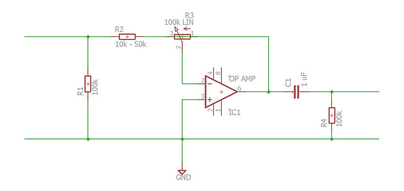
The gain is decided by changing the resistor R2.
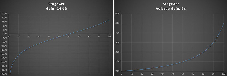
The graphs below show the gain(/attenuation) at 0-100% turn of the linear pot.
14 dB (R2 = 20k ohm):
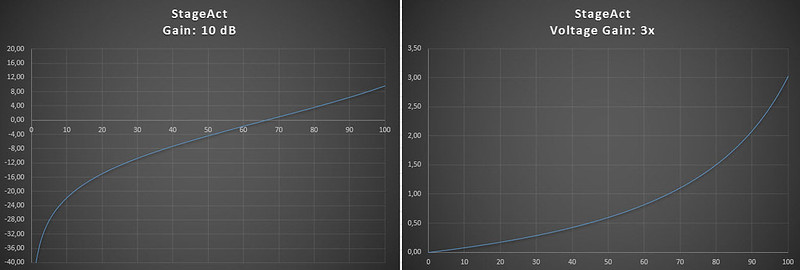
10 dB (R2 = 33k ohm):
6 dB (R2 = 50k ohm):
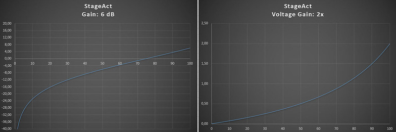
Higher R2 values makes the pot behave less logarithmic. It's still not bad though?
There are a lot of fun things one can do with operational amplifiers. I was thinking about the fact that inverting op amp circuits can have less than unity gain, and that you can use a linear potentiometer and a resistor to simulate a logarithmic pot. What about putting that pot and resistor to use as the gain setting for an inverting op amp circuit?
Nah... It couldn't be that simple. What does the Internet say on the topic?
So I asked Google, and Google came up with this old article:
http://www.schematicsforfree.com/ar... and Op-Amp Make A Tapered Volume Control.pdf
This was how the Single Stage Active Preamp was conceived. Obviously an old idea, but new to me:
The concept uses four components for a stereo preamp. This is obviously not entirely true though. It needs input impedance, output capacitors and bypass capacitors. Still, there are not many pieces to this puzzle. Using a stereo pot and a dual op amp, the total number of components is twelve. This includes two bypass capacitors not show in the picture below:
The gain is decided by changing the resistor R2.
The graphs below show the gain(/attenuation) at 0-100% turn of the linear pot.
14 dB (R2 = 20k ohm):
10 dB (R2 = 33k ohm):
6 dB (R2 = 50k ohm):
Higher R2 values makes the pot behave less logarithmic. It's still not bad though?
Ooooh....
Well, then the gain skyrockets...
Somebody's obviously had this thought before. Any way of remedying that?
Well, then the gain skyrockets...
Somebody's obviously had this thought before. Any way of remedying that?
I used to be head of sound and PA for a church. We had a powered foldback monitor which emitted awful squeaks when the volume control was touched. It turned out to use a similar circuit to yours, so a worn pot created something much worse than silence or a few scratches. I just put a new pot in, but eventually it will start doing it again.
DF96,
I'm sure that was an unpleasant experience, but you learnt something from it. Thanks for making me aware of the problem.
I'm thinking something like this might help:
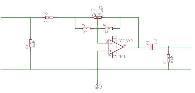
Paralleling the two sections of the pot with much higher resistors. Like 1M and 10M. They will have very little effect in ordinary use, but reduce the volume if the pot fails.
If the pot slider lifts off the track, its resistance will be very high. The 1M/10M will then be effective, equaling 10% turn of the pot. If the pot is shorted the attenuation will be infinite, as in 0% turn of the pot.
I'm quite sure there's a wrong assumption in there somewhere though...
I'm sure that was an unpleasant experience, but you learnt something from it. Thanks for making me aware of the problem.
I'm thinking something like this might help:
Paralleling the two sections of the pot with much higher resistors. Like 1M and 10M. They will have very little effect in ordinary use, but reduce the volume if the pot fails.
If the pot slider lifts off the track, its resistance will be very high. The 1M/10M will then be effective, equaling 10% turn of the pot. If the pot is shorted the attenuation will be infinite, as in 0% turn of the pot.
I'm quite sure there's a wrong assumption in there somewhere though...
Maplin produced a four channel mixer using a similar circuit. It was awful!
Thanks for the info JonSnell,
I'll try to build it, time allowing, and do some measurements. That will hopefully make it clear if it's worth spending time on.
Parallel resistors are one way to tame it. As DIYers we can do this; those doing it for money prefer to save a few pennies by omitting them.
www.hypex.nl/docs/papers/The%20G%20Word.pdf
Same feedback based gain. Potentially same failure mode, but there is a switched resistor version available.
Same feedback based gain. Potentially same failure mode, but there is a switched resistor version available.
www.hypex.nl/docs/papers/The%20G%20Word.pdf
Same feedback based gain. Potentially same failure mode, but there is a switched resistor version available.
Thanks billshurv,
It's cool to see this idea being used elsewhere. I really need to find the time to build and measure this thing.
Look at the APT preamp, and inverting preamp done properly.
I built the circuits as shown 20 some years ago, the pots wear out quickly.
I built the circuits as shown 20 some years ago, the pots wear out quickly.
Look at the APT preamp, and inverting preamp done properly.
I built the circuits as shown 20 some years ago, the pots wear out quickly.
Thanks for pointing me to the ATP preamp, I haven't seen that one before. An op amp based stepped attenuator is a really cool idea. 🙂
This exercise is one of absolute simplicity. Pots are used everywhere, do they really wear out that quickly? The behavior of extremely increased gain when the pot does fail is not very attractive, I hope I've taken care of that. That is at least what the LTSpice simulations tell me.
Last edited:
" do they really wear out that quickly?"
Yes, for some reason or another (I'm not exactly sure why). A stepped attenuator shouldn't have that problem though.
http://p10hifi.net/planet10/TLS/downloads/AptHolmanPreManual.pdf
P.49
Yes, for some reason or another (I'm not exactly sure why). A stepped attenuator shouldn't have that problem though.
http://p10hifi.net/planet10/TLS/downloads/AptHolmanPreManual.pdf
P.49
Last edited:
Yup, that's the same document as I found.
It's cool that the idea I had has been done many times. That might mean it has some potential. Using it as a stepped attenuator is a really great idea, this will be a fun project. 🙂
It's cool that the idea I had has been done many times. That might mean it has some potential. Using it as a stepped attenuator is a really great idea, this will be a fun project. 🙂
pretty similar approach in Musical Fidelity A1
absolutely worst part of amplifier , when tossed away it starts singing
absolutely worst part of amplifier , when tossed away it starts singing
pretty similar approach in Musical Fidelity A1
absolutely worst part of amplifier , when tossed away it starts singing
It's a bit similar, yes. It uses a logpot instead of the loglaw though.
Any theories on why it has a bad effect on the circuit? It's an op amp, among other op amps...
besides fact that practically there is always some DC on pot (reason for wearing , even if smart ones at MF put there blue Alps, and ppl regularly changing even with black Alps  ) , let just call it - nastiness of variable feedback ........ where wicked phase angles are just one of bad things
) , let just call it - nastiness of variable feedback ........ where wicked phase angles are just one of bad thingsThat's a bit discouraging...
I guess that DC would exist whether there's a pot in the way or not? Is it what happens when turning the pot that's bad then?
This part is interesting though:
"Ever switched on the amp with a source playing, and wondered why you get a burst of music (always at much the same level), then silence, then the music at the expected level? When first powered up, the power-amps work almost instantly, but the op-amp is not yet powered. So, the audio signal travels straight via R33, R32, R34 and the volume pot. As the rails start to rise, the op-amp wakes up and the signal is muted until the rails become further established..."
This might mean adding a non-inverting op amp buffer in front of the variable stage... If that's the case, then my simplicity has vaporized.
besides fact that practically there is always some DC on pot (reason for wearing , even if smart ones at MF put there blue Alps, and ppl regularly changing even with black Alps
Where is this DC? If you read putzys he points out that the wiper, being connected to virtual ground, has no current flowing through it (and does it better than I can). Given the measured results of his balanced preamp and the fact that he uses the same topology in his mola mola preamp sugggests that, when implemented correctly its a rather good way of doing it.
- Status
- Not open for further replies.
- Home
- Amplifiers
- Solid State
- StageAct - Four components Preamp