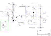
I think I must talk a bit about this amplifier that I call "Amp667". It's a hybrid with a ECC83/12AX7 tube for voltage amplification and mosfet's for the current boost. Perhaps this isn't the right place to start this thread, since it has a vacuum tube. But there is an option to plug in a JFET in place of the tube, and then the amplifier will be 100% solid state. I constructed this one about a year ago.
To obtain an amplification to full voltage amplitude by just using one triode isn't possible. Not even if we use a pentode. So I figured out this solution, which is rather unconventional, I think. The anode is connected to a folded cascode, so the open loop gain will be R5 ( 100k) divided by the cathode resistance, that is around 200. The short NFB path reduces the gain to around 27dB, so the amount of NFB is roughly 18dB. In this configuration the tube will distort no more that 0.2% ( almost exclusively 2:nd order harmonics) at max amplitude, and that's fairly low for a vacuum tube.
Then we have the current amplification section. Here I'm using a solution I figured out perhaps two decades ago, but I haven't used it until now. It's a very short NFB loop around Q3 and the output mosfet's. The stage has unity gain.
Personally, I think this solution is so nice and simple, but I have never seen any such way to create a NFB loop made by other people. Not as DIY or a commercial product. So now I would like you guys to help me with this. Are there any experienced constructors out there that perhaps has seen this solution before? Or perhaps has used one? If so, enlighten me, please! Perhaps the solution even has a name.
The advantages are many:
1. The NFB loop is of course very short.
2. The NFB is only "kicking in" when current is drawn from the output devices. ( Which it of course does all the time, but the NFB will be strengthened when the speaker demands more current )
3. As the frequency rises, the circuit will gradually become some sort of darlington source follower, when C2 takes over at around 30khz. The roll of will be extremely smooth and the circuit will have a very high bandwidth, only limited by the miller capacitances on the output devices, and that means several Mhz.
The section has an amount of NFB that is calculated as 470ohm divided by ( the sum of the source resistance of the two diff mosfet's ). Which will be around 26dB in this case.
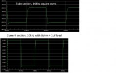
This current section distorts less than 0.02% with a bias of around 600mA. So it is the tube that makes the "sound". I have attached 10khz square wave curves. Note the wave from the current section, and observe that it has 1uF on the output. No ringings at all. This is computer simulated.
When I first auditioned it, I used a brand new TAD tube, and I noticed a subtle "tube" colouration. But I wasn't particularly impressed, so I bought two old tubes from Ebay; one Telefunken and one Philips Miniwatt. When I inserted the Telefunken tube, the sound quality improved drastically. This was a bit of a surprise. Firstly, how could it be so that they made so much better tubes 50 years ago? And secondly, the tube circuitry is made so that it is unusually low distorting, and one wouldn't expect so clearly audible differences.
I mean, if you replace a transistor with another one of a different brand, mostly there are no way to hear that. But tubes obviously makes some sort of distortion that is audible in some way. It couldn't be the 2:nd harmonic, since that is a property of every tube. Well, this is a mystery. But I like mysteries.
OK, I used to listen to the amplifier a lot in the beginning, but I grew tired of it after a while. It was something that annoyed my ears in the long run. After about a year, I looked at the diagram and tried to figure out why my ears objected, and I found a suspicious bootstrapper on the leftmost mosfet. I replaced it with a +60V supply made of a voltage doubler. ( The voltage needed to be higher since the tube section has an output impedance of around 15kohm and if the voltage is taken from the positive rail, then the miller capacitance will induce a visible portion of 2:nd order harmonics ). That bootstrapper apparently fed some portion of the signal back and induced some nervousness in the circuitry.
This turned out to be a hit. Suddenly it sounded as good as it should do theoretically. ( Can anything sound good in theory? )
Constructors usually don't talk about subjective matters, but I'm willing to take a risk. I've used the Philips Miniwatt tube. Btw, that's another good thing, it is easy to switch between different tubes and experiment with sound character since there is only one ECC83 for both channels.
The sound is a bit flamboyant. The dynamics are very good. The tube puts a certain quality to the perceived sound. It's obviously colouring a bit, but only subtle. People who are totally hooked up on solid state probably will object a bit, but then there is an option to replace the tube with a JFET.
The sound is chiselled out in a very exact way, but the midrange still has an addictive, pleasant round quality. The treble is clear but not sharp.
I have attached the real schematics below.
You're welcome to visit my site and check out other projects:
Embuddy
An externally hosted image should be here but it was not working when we last tested it.
To obtain an amplification to full voltage amplitude by just using one triode isn't possible. Not even if we use a pentode. So I figured out this solution, which is rather unconventional, I think. The anode is connected to a folded cascode, so the open loop gain will be R5 ( 100k) divided by the cathode resistance, that is around 200. The short NFB path reduces the gain to around 27dB, so the amount of NFB is roughly 18dB. In this configuration the tube will distort no more that 0.2% ( almost exclusively 2:nd order harmonics) at max amplitude, and that's fairly low for a vacuum tube.
Then we have the current amplification section. Here I'm using a solution I figured out perhaps two decades ago, but I haven't used it until now. It's a very short NFB loop around Q3 and the output mosfet's. The stage has unity gain.
Personally, I think this solution is so nice and simple, but I have never seen any such way to create a NFB loop made by other people. Not as DIY or a commercial product. So now I would like you guys to help me with this. Are there any experienced constructors out there that perhaps has seen this solution before? Or perhaps has used one? If so, enlighten me, please! Perhaps the solution even has a name.
The advantages are many:
1. The NFB loop is of course very short.
2. The NFB is only "kicking in" when current is drawn from the output devices. ( Which it of course does all the time, but the NFB will be strengthened when the speaker demands more current )
3. As the frequency rises, the circuit will gradually become some sort of darlington source follower, when C2 takes over at around 30khz. The roll of will be extremely smooth and the circuit will have a very high bandwidth, only limited by the miller capacitances on the output devices, and that means several Mhz.
The section has an amount of NFB that is calculated as 470ohm divided by ( the sum of the source resistance of the two diff mosfet's ). Which will be around 26dB in this case.
This current section distorts less than 0.02% with a bias of around 600mA. So it is the tube that makes the "sound". I have attached 10khz square wave curves. Note the wave from the current section, and observe that it has 1uF on the output. No ringings at all. This is computer simulated.
When I first auditioned it, I used a brand new TAD tube, and I noticed a subtle "tube" colouration. But I wasn't particularly impressed, so I bought two old tubes from Ebay; one Telefunken and one Philips Miniwatt. When I inserted the Telefunken tube, the sound quality improved drastically. This was a bit of a surprise. Firstly, how could it be so that they made so much better tubes 50 years ago? And secondly, the tube circuitry is made so that it is unusually low distorting, and one wouldn't expect so clearly audible differences.
I mean, if you replace a transistor with another one of a different brand, mostly there are no way to hear that. But tubes obviously makes some sort of distortion that is audible in some way. It couldn't be the 2:nd harmonic, since that is a property of every tube. Well, this is a mystery. But I like mysteries.
OK, I used to listen to the amplifier a lot in the beginning, but I grew tired of it after a while. It was something that annoyed my ears in the long run. After about a year, I looked at the diagram and tried to figure out why my ears objected, and I found a suspicious bootstrapper on the leftmost mosfet. I replaced it with a +60V supply made of a voltage doubler. ( The voltage needed to be higher since the tube section has an output impedance of around 15kohm and if the voltage is taken from the positive rail, then the miller capacitance will induce a visible portion of 2:nd order harmonics ). That bootstrapper apparently fed some portion of the signal back and induced some nervousness in the circuitry.
This turned out to be a hit. Suddenly it sounded as good as it should do theoretically. ( Can anything sound good in theory? )
Constructors usually don't talk about subjective matters, but I'm willing to take a risk. I've used the Philips Miniwatt tube. Btw, that's another good thing, it is easy to switch between different tubes and experiment with sound character since there is only one ECC83 for both channels.
The sound is a bit flamboyant. The dynamics are very good. The tube puts a certain quality to the perceived sound. It's obviously colouring a bit, but only subtle. People who are totally hooked up on solid state probably will object a bit, but then there is an option to replace the tube with a JFET.
The sound is chiselled out in a very exact way, but the midrange still has an addictive, pleasant round quality. The treble is clear but not sharp.
I have attached the real schematics below.
You're welcome to visit my site and check out other projects:
Embuddy
Attachments
I take my hat off to you, Svitjod (would that be SwedeGod?).
This is one of the most innovative and modestly described circuits I've ever seen in audio.
This is up there with NP, VladimirK, and Alex Nikitin. It really is extraordinary; you effortlessly combine tube with SS with flair for both.......
Your awareness of the art of audio design is beautifully explained. I too have found bootstrap sound and cannot explain it either. I hope the luminaries, particularly Bob Cordell, see this...... wonderful!!
Thank you for giving us this circuit, something of a gift........
Hugh
Are there any experienced constructors out there that perhaps has seen this solution before? Or perhaps has used one? If so, enlighten me, please! Perhaps the solution even has a name.
The "Genesis stealth" class A amp used a similar differential based
feedback loop in it's current stage. One of the lowest THD OPS's
I've ever simulated in isolation.
OS
Really nice to get some positive reactions. I have had some entrepreneur dreams over the years, but decided recently to present my various constructions here on Diyaudio instead of trying to make money on them.
But it's not easy to get some attention, my previous threads have gone almost unnoticed. Even my most ambitious project that I call "Amp1" didn't get one single reply.
Amp1_system
OK, ostripper, you were the guy who had enough experience. Usually, when you figure out something you think is clever, there is always someone before you. But that doesn't matter, so long it isn't patented or used as a DIY project.
BTW, I got my site wrong, here it is:
Embuddy
And the name Svitjod, that's the Icelandic name for Sweden.
One more thing. There must be thousands of interesting diagrams over various circuits here on Diyaudio, but they will soon start climbing downwards and become obsolete. Usually, the posts that get the most replies are enthusiastic but rather crappy constructions that provokes people to respond and those posts will remain active a long time. Wouldn't it be good if we had a database over DIY constructions?
Hi Guys
Note that tubes have a break-in period of about 100 hours. A fresh tube will sound bright and harsh compared to one broken in. Many people are swayed by sales reps to replace the tubes when the tone changes. This is a mistake. At that point of tone change, the tube is broken in and won't change its sound for the rest of its life - decades of use most people waste.
Of the various tube-SS hybrids I've built, I prefer the ones where the tube is allowed to do its thing and sound like a tube. Circuits that load the tube with current-mirrors, current-sources, etc or cascode the tube with SS devices tend to lose a lot of the tube character albeit at the benefit of better performance. It isd good that you can still hear the differences of the tube in your circuit. With due care, it is possible to achieve less than 0.01% THD with tubes alone.
Have fun
Construction is very well done, as for the electronics i simulated the final stage, its perfs are correct THD wise but contrary to what is claimed it is higher at 10KHz than at 1KHz, at least for this stage.
Attachments
Intersting, Struth. I didn't think of braking in the new TAD tube - I used it perhaps 10 hours max before I changed. I will immediately insert my TAD and start breaking it in, and I will return in a couple of hundred hours with a report.
I see your point with letting the tube reveal it's tubeness without any paraphernalia.
But I was thinking like this. I had recently finished my most ambitious project, which I call Amp1. My purpose was to maximize soundquality to it's maximum - at least I couldn't do anything better than that. It sounds absolutely stunning, but one gets used to everything, and suddenly it began itching in my constructor-fingers, but it was no point continue that performance race, so I decided to experiment with things, such as tube sound.
Since I'm no true believer, I came up with this thing, and the reasons are:
You can't get full voltage swing with just one troide or pentode, I,m pretty shure of that, if the THD should be acceptable. Actually, that folded cascode is acting a bit like the second grid of a pentode.
Secondly, the advantage with this solution is that there is only one physical tube, and it will be easy to experiment with different brands, and this particular type is fairly cheap.
OK, the really interesting thing is that the character of the tube comes through so clearly, despite very low THD figures. So personally, I believe that there are some undocumented mechanisms that sets the character of a tube. Not just 2:nd or third order harmonics.
I have a formula over the transfer function that I took from a school book.
Ia = k( 1 - Ugk/Us)^(3/2)
What makes the difference to a mosfet is that 3/2 ratio. On a mosfet it is just 2, or a simple square law. This is probably why many prefer mosfet's and tubes, the bipolars has an exponential transfer function and contains much more overtones.
Well, in real life it isn't that simple. A complementary pair, class A biased, should theoretically not distort anything at all, since the two square laws will cancel each other out, but in real life this doesn't happen.
OK, some traditionalists may be worried about that cascode transistor. I just say that this transistor really is a more effective version of the second brid of a pentode.
I have made another horrible hybrid that I have documented on my site.
- Embuddy
Thank's Wahab for your simulation, you have a better spice software than I, what's it's name?
Actually, I didn't claim the THD to be the same at 1 and 10 khz, but there is no big difference, and I'm a bit surprised you got so low figures.
If it was important for me to get minimal THD, I could have used a stronger NFB, but I think this works best if you bias the output stage at appr 600mA total for the two pairs of mosfet's.
I think too heavy NFB makes the sound nervous. It's like if you are balancing on one leg, and you are extremely cautious on doing it properly. If we are over ambitious doing so, we tend to tremble and wiggle, since our nervous system( which acts as a kind of NFB loop) is overly tensed. But if you relax in this balancing act, you will stand more steadily and you will only waver slightly back and forth. I think that's a good analogy with a heavy NFB loop, and why we should avoid it.
OK, I can't resist talking a bit more.
The really interesting thing is the current section - it performs very well, both subjectively and objectively. It is very transparent, so I thought a tube would be nice as some sort of "spice" that gives the amp some character.
So I think it's good that the tube doesn't take over too much.
Then the amp can be used with a jfet. If you aren't interested in tubes whatsoever, the circuit may be redesigned with a lower voltage, and other minor alterations.
Btw, I have some PCB layouts if you want to start building.
Hi Guys
I like this circuit but can't follow one point made above:
" open loop gain will be R5 ( 100k) divided by the cathode resistance, that is around 200"
Rk=10k which would suggest a gain of only 20 not 200. How do you get 200?
"Are there any experienced constructors out there that perhaps has seen this solution before? Or perhaps has used one?"
The output buffer is a lot like the high-performance voltage follower Self works up to in the Small Signal book.The starting point he refers to as a "simple Schlotzaur circuit", and this resembles yours except for your addition of the RCs between the feedback device and the upper output device gate. His circuit uses BJTs but otherwise the function is the same. Your use of mosfets provides a bit more voltage compliance between the input device drain and the following gate to let the RCs do their thing. Overall THD is likely to be higher with the mosfets vs BJTs.
Have fun
Last edited:
Member
Joined 2009
Paid Member
This hybrid folded cascode has been suggested before but I've never seen it built. It's related to the Taylor follower topology.
http://www.diyaudio.com/forums/solid-state/194268-dx-hybrid-amplifier-will-produced-soon.html
http://www.diyaudio.com/forums/tubes-valves/211354-does-3a5-have-stones-drive-2a3.html
As another option, you could use a tube for the LTP bit in the middle, something like a 12AU7 will run off the low supply voltage.
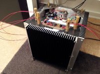
I like your design but even more I like the build - looks great.
There's a lot of scope for hybrids, seems like a rich vein for further exploring. I've yet to build one - so far either SS amps or tube amps but one day....")
http://www.diyaudio.com/forums/solid-state/194268-dx-hybrid-amplifier-will-produced-soon.html
http://www.diyaudio.com/forums/tubes-valves/211354-does-3a5-have-stones-drive-2a3.html
As another option, you could use a tube for the LTP bit in the middle, something like a 12AU7 will run off the low supply voltage.
I like your design but even more I like the build - looks great.
There's a lot of scope for hybrids, seems like a rich vein for further exploring. I've yet to build one - so far either SS amps or tube amps but one day....
Last edited:
Thank's Wahab for your simulation, you have a better spice software than I, what's it's name?
It is available here, there s a free version that is enough for most designs :
Free Demo, SIMetrix/SIMPLIS analog circuit simulation software
Actually, I didn't claim the THD to be the same at 1 and 10 khz, but there is no big difference, and I'm a bit surprised you got so low figures.
You are right, it was said for your other thread/project.
As for the values dont forget that it s with a unity gain power stage.
If it was important for me to get minimal THD, I could have used a stronger NFB, but I think this works best if you bias the output stage at appr 600mA total for the two pairs of mosfet's.
The sim i made are at 600mA/device, at half this current the amp will switch in class B at some point, although class A is not needed for the whole power range, a few watts are more than enough.
I think too heavy NFB makes the sound nervous. It's like if you are balancing on one leg, and you are extremely cautious on doing it properly. If we are over ambitious doing so, we tend to tremble and wiggle, since our nervous system( which acts as a kind of NFB loop) is overly tensed. But if you relax in this balancing act, you will stand more steadily and you will only waver slightly back and forth. I think that's a good analogy with a heavy NFB loop, and why we should avoid it.
More NFB, if correctly applied , will yield a more linear amp, so should we conclude that an amp that is more linear is not as good sounding.??.
Last edited:
Hi Guys
To my mind, the distortions created by electronic circuits are unnatural inasmuch as we did not evolve exposed to such distortions. They are entirely new in a geologic sense. I think that since we use electronics for purposes of communication and for entertainment, it is important to reduce the attendant distortions to the lowest value possible so that what remains sounds as "naturall" as possible. I also don't think that you need a "golden ear" to be bothered or fatigued by many of the distortions present in electronic equipment, even if the quantity is extremely low as measured.
Baxandall showed what happens in a single gain stage with moderate open-loop gain. As open-loop gain is increased relative to the closed-loop gain, the distortion products bloom at a modest ratio but then fall dramatically once there is an increase in feedback. The point where the distortions are highest is in the "modest amount of feedback" range that many builders feel is "correct". Of course, much of the character of the distortion profile depends on the circuit.
As others have suggested, there are likely attributes of amp performance that have not yet been defined but which bear great importance on what we hear and feel. I think the control theory approach to amp design has its limitations - and even Self has stated this in APAD6. For example, in my sims control theory would suggest that a given design should be unstable yet it has super low THD and very wide bandwidth and is stable into all kinds of load. The phase response curve "follows" the amplitude response curve. I see plots on this forum that look like a roller-coaster and the THD is not so great but the designs are applauded and meet control theory guidelines.
I don't know if there is a good/bad difference or conclusion with respect to low feedback and high feedback. It is maybe more of a total system synergy that must be achieved.
Have fun
Last edited:
Hi Guys
Hugh: No reference to the bypass cap was made in the statement of how the gain is calculated.I know Ck is there. I would still like to see an explanation of the actual gain calculation from Svitjod.
The voltage gain exhibited by the tube will be miniscule inasmuch as its plate barely moves. The "visible" gain comes from the second stage.
Have fun
Member
Joined 2009
Paid Member
The voltage gain exhibited by the tube will be miniscule inasmuch as its plate barely moves. The "visible" gain comes from the second stage.
Exactly. When I first looked at this approach (see my links posted above) I called it a 'Pentode wired triode' - there is no longer any sensitivity to the plate voltage now that it's fixed. The tube operates purely as a transconductance amplifier. Without any plate movement the load line is near vertical. This is not the typical way to operate a triode and the 'sound' will be different. It said that a triode has internal feedback- the current flow depends on plate voltage so as the plate voltage varies with signal it affects the current - the plate load provides local degeneration. With this hybrid that doesn't happen. The plate moves only because the bipolar devices requires some Vbe movement. The fabled linearity of the triode input tube is not being used here in the normal sense. Perhaps it is simply converting a high input impedance (minuscule current flow at it's grid) to a low output impedance (minuscule voltage swing at its plate) as is needed to drive the emitter of the bipolar device ?
Last edited:
Yes, the triode is working into a near short-circuit so it will maximise distortion. Cascodes always do this, which is why they should only be used for small signal stages. The first stage open-loop gain will be approximately gm x 100k. I would expect open-loop gain in the region of 150, not 200.
The 'inverting opamp' configuration of the input stage will add some thermal noise from the 39k resistor, but this might not be too serious for a power amp.
I find the output stage confusing. It appears to have a mix of positive and negative feedback. Positive feedback to the source, and negative feedback to the gate of the second LTP FET. Or is this some form of loop stabilisation network?
I find the output stage confusing. It appears to have a mix of positive and negative feedback. Positive feedback to the source, and negative feedback to the gate of the second LTP FET. Or is this some form of loop stabilisation network?
There s no miller compensation in the main foward path, the network that goes to the differential nodal point act as feedfoward drive of the output stage at high frequencies.
OK. I think I see it now.
I would have said the opposite. The ECC83/12AX7 is used in about the most distorting circuit possible (apart from those who bias it wrongly too) but this is then fixed up by around 15-20dB local negative feedback.Svitjod said:And secondly, the tube circuitry is made so that it is unusually low distorting, and one wouldn't expect so clearly audible differences.
Sorry, I got that wrong. The '100k' should be 100k in parallel with 820k, or about 89k. A bit less open-loop gain. This gain will fall below about 25Hz due to the small cathode decoupler value of 10uF. Fortunately, the feedback will deal with this so the net result will be a rolloff somewhere around 3Hz (plus the other passive rolloffs in the same frequency region).DF96 said:The first stage open-loop gain will be approximately gm x 100k.
Rk is actually bypassed by a capacitor. But I was wrong with the transconductance. It should be 1/(500ohm). OLG will be 100k/ 500 = 200. Closed NFB makes it to around 22 or 27dB. The circuit works, I use to listen to it!
That RC thing sets the NFB factor and the bandwidth. Douglas is a hardcore rationalist and he cannot see why max NFB not should be applied. Mosfet's are superior here, since the circuit can be made simpler.
This circuit is'n used very often since gain normally has to be applied, and why not do it in one step? But in this tube case, the circuit is motivated.
Actually, I think it's rather balanced. One of my favorite ideas is that if NFB has to be applied, the loop should be short and not have to much NFB. The tube has a loop around two active elements and the SS stage also has a loop around two elements. Neat. And furthermore, the tube stage gives around 0.2 % 2:nd order harm, and the SS stage gives around 0.01% H2 and H3,H4. This is ideal according to many. The H2 will dominate and mask the odd ones.
So theoretically, or should I say philosophically, this amp is pretty much ideal.
But Ostripper won't approve, I'm sure.
- Status
- This old topic is closed. If you want to reopen this topic, contact a moderator using the "Report Post" button.
- Home
- Amplifiers
- Solid State
- Some in-depth talk about my "Amp667" power amplifier