
No.
Although the schematic does not show the values and type of the components used I's still say this is not a good schematic.
They use an opamp to drive a common emitter power stage (let's suppose/hope that is stable) which should have plenty of gain on its own. But then they add a two transistor pre-amplifier?
And how does the loading of the output darlington work? Current source? Maybe wrongly drawn?
Do not built it, but that's my 2 cents...
EDIT:
Mooly is right too, the darlington lower stage also seems wrongly drawn!
EDIT 2:
The feedback of the preamplifier is a bit undefined as well. Rubbish schematic")
Although the schematic does not show the values and type of the components used I's still say this is not a good schematic.
They use an opamp to drive a common emitter power stage (let's suppose/hope that is stable) which should have plenty of gain on its own. But then they add a two transistor pre-amplifier?
And how does the loading of the output darlington work? Current source? Maybe wrongly drawn?
Do not built it, but that's my 2 cents...
EDIT:
Mooly is right too, the darlington lower stage also seems wrongly drawn!
EDIT 2:
The feedback of the preamplifier is a bit undefined as well. Rubbish schematic
Last edited:
This will simply not work period. Waste of time and money. Plenty of simple yet good designs on this forum.
The site it comes from: http://www.brighthubengineering.com...439-build-this-simple-class-a-test-amplifier/
The site it comes from: http://www.brighthubengineering.com...439-build-this-simple-class-a-test-amplifier/
Last edited:
klh₂₀₀₀;4488942 said:Where can i find some designs on this forum then?
… everywhere … there are hundreds, maybe thousands of schematics throughout this forum. No, nobody is going to spoon-feed them to you, either! The point is to look around, learn a bit, look some more, learn some more.
Finally, if you are going to draw schematics, do try to follow the conventions about traces crossing components. For example, the output of the OpAmp crossing R₈ 'underneath'.
More problems (if you're still interested)
T₁ base connected via R₅ to T₂'s emitter? Seems pointless. R₇ sitting on top of the trace running from C₂ to OA '-' input? And OA '-' input connected directly to emitter of T₄? Others have comment that T₅ & T₄ are not in a darlington configuration. Same for T₇ and T₆.
Since you also have lines-crossing-lines, but without an indication as to whether they are connected or “just crossing don't you know?”, there's no way to tell (given all the other circuit inconsistencies and errors) whether they're intended to be connected, or just passing through.
Finally, there's the observation of others that there's a "preamplifier on an op-amp", which is kind of like putting a firehose onto a squirt-gun. Just doesn't make sense.
Good luck! Read up more!
GoatGuy
I suspect the op is looking for something fairly simple and that uses common parts.
The JLH69 has to be a main contender, very simple, excellent performance and very forgiving.
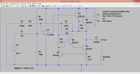
Is this a good jlh69 schematic?

Sent from my iPad using Tapatalk
Since I am an enthusiastic constructor of mostly class A amps, I recommend you to take a look at my constructions.Where can i find some designs on this forum then?
Firstly you can look at the Yoga amp I posted e week or two ago on this Solid state thread.
Another that I like is my NDH mosfet amp:
http://www.diyaudio.com/forums/solid-state/96192-post-your-solid-state-pics-here-433.html#post4472144
Then we have Nelson Pass First Watt amps.
The only reason to use class A operation is to make amps that has low negative feedback and a healthy simple circuit topology. I mean, If you construct an amp with a lot of stages and perhaps an IC and then apply a massive global feedback, then we don't really have any use for class A operation, do we?
I don't agree........................................
The only reason to use class A operation is to make amps that has low negative feedback and a healthy simple circuit topology. I mean, If you construct an amp with a lot of stages and perhaps an IC and then apply a massive global feedback, then we don't really have any use for class A operation, do we?
The amplifier is usually ClassA upto, but not including the final stage.
Generally only that final stage varies between ClassA and ClassAB.
Both can be with or without global negative feedback.
Both can be low levels of GNFB
Both can be high levels of GNFB
The ClassA or ClassAB nature of the output stage does not determine whether the amp is low global feedback, nor whether either will benefit from GNFB
The usual premise is to design the amplifier for very good performance. Then close the GNFB to define the feedback and get the parameters that come from using GNFB.
One does not start with a badly performing amplifier and hope (meaning no design expertise) that GNFB might improve on that bad performance.
One does not start with a badly performing amplifier and hope (meaning no design expertise) that GNFB might improve on that bad performance.
Personally, I believe that most class A amps are designed by people who desires to maximize the subjective aspects. If you construct a class B amp that has perhaps 0.01% THD over the entire audio range, then if we screw up the bias to a couple of amps, then the dist will go down towards 0.0001%, and that's not a path those guys are interested in.
Those guys ( including myself) usually follow that old "truth" that GNFB usally makes the sound less enjoyable. The amps tends to sound a bit nervous or at least perceived as less vivid. That's the general belief in the subjectivist school. So, from that point of view, using class A gives the designer tools to make the amps simpler and with a lower NFB without a lot of THD.
Rational designers use to concentrate on lower the THD as a whole. Some believe that the kind of overtones matters. For example, very many overtones usually sounds worse that just one type, such as 2:nd harmonics, even though they have a lesser amplitude. NFB tends to complicate the THD pattern even more.
Do you agree on this?
I think one possible reason for class A is having (pretty much) guaranteed distortion reducing monotonically as signal levels decrease. The usual practice of measuring distortion only at some high power level might give a rather irrelevant number -- on a speaker with moderate to high sensitivity, signals peak above 1 watt for only a small portion of the time (take an oscilloscope to your speaker terminals during playback to see). A more relevant realistic measure of amplifier distortion might be on the order of tens to hundreds of milliwatts, where a lot of ambience (in particular) is heard between relative tonal blasts. Most of what you hear can be when the amp is putting out nearly nothing. Some (most maybe?) class AB amps will have distortion that is proportionally higher near low levels than at higher levels, particularly with the temperatures of the output devices' junctions swinging around over time during play. Going class A makes that scenario quite unlikely.
But I believe class D also has that benefit.
Measuring distortion (only) at low level can be hard to do, though, as noise becomes a limiting factor in the measurement. You have to do a lot of acquisitions (or a very long one) and synchronously average to be able to see below the noise at low levels. For DIYers, making a class A amp (maybe class D?) gets there without the measurement complications.
Last edited:
About that JLH10 Amp that KLH2000 fund a schematic over. This circuit is quite original. Tr3 is some sort of phase splitter, but on valve designs the splitter works on voltage. This one works on current. One can say that r100 sets a bias current and Tr3 is some sort of subtraction device. When the upper half gets more current, the lower output half gets proportionally less. It's like an analog flip flop.
The interesting thing is that since the Tr1-Tr3 package really is current driven at high impedance and the ordinary Vbe exponential curve is replaced with the hfe curve.
That may be why many perceive this amp to be tube-like sounding. But some reported a dull midrange though. Perhaps this has to do with the fact that the hfe of the 2N3055 weakens rapidly when current rises.
So this design should be used with modern bipolars such as Sanken. Even Tr3 benefits from a linear hfe.
My old Rotel RB970 - clone had a couple of 2sc1047 I think it was. The had a rather linear hfe up to about 3A.
But I recommend a more up to dete design.
- Status
- This old topic is closed. If you want to reopen this topic, contact a moderator using the "Report Post" button.
- Home
- Amplifiers
- Solid State
- Did class A amplifier. Is this schematic good?