I just replaced the NTC thermistor on the "AC input & protection circuit" board. I thought I photographed all the cables before removing the board, but I discovered I failed to photograph the cables on the edge of the board facing the front panel.
The lowermost two 2-pin connectors on the front edge are labeled, starting at the bottom, "TMP LED" and "TMP SW".
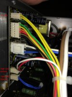
There are two cables that fit these connectors, and I hope someone can help me avoid swapping them. One cable has two blue wires and passes through a hole in the metal bottom plate close to the connector. The other cable has one red and one white wire and extends to a hole at the right end of the front panel.
I've attached a photo of what I guess is the correct arrangement: the blue/blue cable is connected to the lowermost connector TMP LED. Is this correct, or do I have the two cables reversed?
Thanks for your help!
The lowermost two 2-pin connectors on the front edge are labeled, starting at the bottom, "TMP LED" and "TMP SW".
There are two cables that fit these connectors, and I hope someone can help me avoid swapping them. One cable has two blue wires and passes through a hole in the metal bottom plate close to the connector. The other cable has one red and one white wire and extends to a hole at the right end of the front panel.
I've attached a photo of what I guess is the correct arrangement: the blue/blue cable is connected to the lowermost connector TMP LED. Is this correct, or do I have the two cables reversed?
Thanks for your help!
Attachments
Use your DVM on diode check to find out which one has the switch and which one has the LED.
Thanks, Jon — that resolved it!
You can tell how rusty I am that I didn't think of that. I haven't done hardly any tinkering since the 1960's when I used to build ham radio gear. No diode check function on the VTVM's back then!
")
Thanks again for your patience with a reborn neophyte.
- Status
- This old topic is closed. If you want to reopen this topic, contact a moderator using the "Report Post" button.