I found this old circuit,
I remember building it years ago.
I have no idea where it came from..perhaps someone may know?
It was just drawn on a scrap of paper.
I thought it might be interesting for someone.
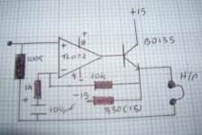
No coupling caps.
You can use it to drive cables as well (Buffer)
Regards
M. Gregg
I remember building it years ago.
I have no idea where it came from..perhaps someone may know?
It was just drawn on a scrap of paper.
I thought it might be interesting for someone.
No coupling caps.
You can use it to drive cables as well (Buffer)
Regards
M. Gregg
Attachments
Last edited:
45mA of bias current? Where to? Through the headphones?
Have I fallen asleep with my eyes open, again?
Add A DC blocking capacitor to protect the headphones.
Add a load so that the output transistor can flow some bias current.
Through the 330r resistor which goes to -15V.
There should be no significant offset.
It's a very common design, but has way too much gain for most applications.
45mA of bias current? Where to? Through the headphones?
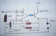
No. +15V -> BD135 -> 330 Ohms -> -15V.
The weak points are:
- (Very) prone to (V)HF oscillation. Add at least a base stopper resistor (~100 Ohms).
- Asymmetric clipping produces DC offset at clipping.
- Make sure the BD135 has high current gain (BD135-16)
- No DC protection for the headphones in case of component failure or DC at the input.
No. +15V -> BD135 -> 330 Ohms -> -15V.
The weak points are:
- (Very) prone to (V)HF oscillation. Add at least a base stopper resistor (~100 Ohms).

I can't remember which Op amp I used Lm833 possibly I remember trying a few different ones..and a small Heat Sink on the BD135...
I'm sure I had another version of this as well...
Regards
M. Gregg
Attachments
Last edited:
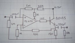
Now I see a connection via 150r to Vee.
I can't remember which Op amp I used Lm833 possibly I remember trying a few different ones..and a small Heat Sink on the BD135...
I'm sure I had another version of this as well...
Regards
M. Gregg
But the 330r looked to me as open ended.
Now I can see why I misread it.
- Status
- This old topic is closed. If you want to reopen this topic, contact a moderator using the "Report Post" button.
- Home
- Amplifiers
- Solid State
- HP amp circuit just for interest