Hi DIYaudio members. I am new here so let me introduce myself.
I am a long-time audio hobbyist and I have been lurking here for quite some time. I have been mainly building full tube amplifiers but I have also done TDA1541 DAC’s, MP3 players and so on.
I have registered here because I’d like to see the pictures (there are some very nice projects here !) but I also want to share a new project with the community which I think has some interesting features: The “Dahlia” amplifier!
A bit of history…
My current living room amplifier is a large 6550 ultra-linear full tube amplifier. In order to get an acceptable “WAF” (Woman Acceptance Factor") ) and to fit our TV cabinet I mounted the power tubes inside and lying down. Bad idea as it turned out…. The amplifier just eats EH6550 tubes! I am also not quite content with the sound. It is missing the wow factor that some of my previous amps had. So, I figured I needed something new. I wanted something completely different than what I am used to so I decided to design a hybrid amplifier. I also decided that the new amplifier had to be affordable.
) and to fit our TV cabinet I mounted the power tubes inside and lying down. Bad idea as it turned out…. The amplifier just eats EH6550 tubes! I am also not quite content with the sound. It is missing the wow factor that some of my previous amps had. So, I figured I needed something new. I wanted something completely different than what I am used to so I decided to design a hybrid amplifier. I also decided that the new amplifier had to be affordable.
As I started doing some SPICE simulations I quickly figured out that the power stage of a hybrid design is probably the most critical stage in the whole amplifier. My first attempts were feeding the output of a tube stage into a FET buffer(for the impedance matching) that drove a push-pull emitter follower final stage. The final stage produced a lot of uneven harmonics (due the symmetrical nature) and, worst of all, crossover distortion when operated in class AB. This thus defeated the point of having a tube in the first place as the harmonic signature of the tube was totally killed by the distortion of the output stage. So, that design was discarded. Back to the drawing board….
On the second attempt (or third, or fourth….) I had the tube feeding into a single ended CCS loaded emitter follower. That looked much better! The single ended emitter follower always operates in class A (no crossover nastiness) and has a harmonic signature that is much more “tube-like”. A single ended emitter follower also has very low distortion so that the total distortion is dominated by the tube. When operated without any global feedback I could probably get a nice smooth triode sound that is very “tuby”.
However, there is a catch, the single-ended emitter follower is extremely inefficient at only 20%. So, this means large heatsinks and power supplies for any reasonable output power. The concept of a tube + single ended emitter follower is of course not new. It is also used by some headphone amplifiers. However, there power levels are low, I want to drive speakers!
The company I work for had a large surplus of 19V/4.7A SMPS adapters. As I have 4 Ohm speakers I figured I could make a nice 2*8W amplifier with this adapter and the circuit I designed. 8W is a reasonable amount of power for my room. Only problem remaining was that I would still need to dissipate about 70W continueosly ! Not impossible of course but still quite a lot. Heatsinks cost money too!
So I started thinking and experimenting and I finally found a satisfying solution. This is And this is where the name "Dahlia" comes in. Dahlia stands for “Dynamic Class A Hybrid Amplifier”.
Dynamic Class A.
The solution for the heat problem is to dynamically adjust the bias of the amplifier according to needed power. My amplifier will run 99% of the time at only a few 100 milliwatts and even when I push it will only rarely run at the full 8W. Music is very dynamic and the “crest” factor (= difference between average power and peak power) is often a factor 10 of higher. So, the average amount of power needed (and thus dissipated) can be reduced tenfold.
Now, dynamic class A is nothing new. Many amplifiers use steered current sources to reduce the dissipation. However, those amplifier use the input signal to directly modulate the current source. Dahlia does it differently. Dahlia measures the current going through the output transistor and then regulates the current source so that the output transistor stays in class A. Dahlia also has a memory function. It will increase the bias very quickly when needed but decrease the bias very slowly. So, the current through the current source does not vary directly with music (otherwise it would almost be some push-pull like design) but it varies with the peak power.
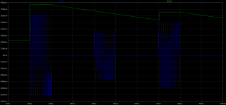
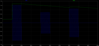
Maybe it is best to show how the bias current varies with some simulation plots. The first plot shows Dahlia driving an 8 ohm load. The blue line is the current through the load. The green line is the current through the current source, this is the bias current. The plot shows how the bias current varies when 3 successive 1kHz sine burst are fed into Dahlia. Initially, the bias current is low, ~220mA. When the first burst hits, the bias current is immediately ramped up to almost 800mA and stays there for the duration of the burst. So, the first edge of the first sine of the burst may see some distortion as the current through the emitter follower has to change very non-linearily. The rest of the burst is clean however. So this distortion, even though it is very small, only exists for a very short time period. As a result, this distortion is not audible (at least to my ears). The plot also shows how the successive burst are handled, the bias is lowered slowly and is still sufficient high to handle the second burst. When the third burst hits bias is again slightly raised. The second picture shows the same signal but then for a 4 Ohm load. As you can see Dahlia will adjust bias accordingly.
So, Dahlia adjusts the bias dynamically based on the peak level of the bias current needed by the load. In practice this results in a much reduced power consumption and hence smaller heatsinks are needed. I think this is pretty neat! Maybe it has been done before but I couldn’t find any design that does something similair.
In the next post I will discuss the schematic and post some pictures of the version I made. The final design uses all jellybean components so should be easy to build. In fact, a colleague of mine built one out of some components he had lying around. The total bill for the stuff he didn’t had was only 25 euros.
Mathesar
I am a long-time audio hobbyist and I have been lurking here for quite some time. I have been mainly building full tube amplifiers but I have also done TDA1541 DAC’s, MP3 players and so on.
I have registered here because I’d like to see the pictures (there are some very nice projects here !) but I also want to share a new project with the community which I think has some interesting features: The “Dahlia” amplifier!
A bit of history…
My current living room amplifier is a large 6550 ultra-linear full tube amplifier. In order to get an acceptable “WAF” (Woman Acceptance Factor
) and to fit our TV cabinet I mounted the power tubes inside and lying down. Bad idea as it turned out…. The amplifier just eats EH6550 tubes! I am also not quite content with the sound. It is missing the wow factor that some of my previous amps had. So, I figured I needed something new. I wanted something completely different than what I am used to so I decided to design a hybrid amplifier. I also decided that the new amplifier had to be affordable.As I started doing some SPICE simulations I quickly figured out that the power stage of a hybrid design is probably the most critical stage in the whole amplifier. My first attempts were feeding the output of a tube stage into a FET buffer(for the impedance matching) that drove a push-pull emitter follower final stage. The final stage produced a lot of uneven harmonics (due the symmetrical nature) and, worst of all, crossover distortion when operated in class AB. This thus defeated the point of having a tube in the first place as the harmonic signature of the tube was totally killed by the distortion of the output stage
. So, that design was discarded. Back to the drawing board….On the second attempt (or third, or fourth….) I had the tube feeding into a single ended CCS loaded emitter follower. That looked much better! The single ended emitter follower always operates in class A (no crossover nastiness) and has a harmonic signature that is much more “tube-like”. A single ended emitter follower also has very low distortion so that the total distortion is dominated by the tube. When operated without any global feedback I could probably get a nice smooth triode sound that is very “tuby”.
However, there is a catch, the single-ended emitter follower is extremely inefficient at only 20%. So, this means large heatsinks and power supplies for any reasonable output power. The concept of a tube + single ended emitter follower is of course not new. It is also used by some headphone amplifiers. However, there power levels are low, I want to drive speakers!
The company I work for had a large surplus of 19V/4.7A SMPS adapters. As I have 4 Ohm speakers I figured I could make a nice 2*8W amplifier with this adapter and the circuit I designed. 8W is a reasonable amount of power for my room. Only problem remaining was that I would still need to dissipate about 70W continueosly ! Not impossible of course but still quite a lot. Heatsinks cost money too!
So I started thinking and experimenting and I finally found a satisfying solution. This is And this is where the name "Dahlia" comes in. Dahlia stands for “Dynamic Class A Hybrid Amplifier”.
Dynamic Class A.
The solution for the heat problem is to dynamically adjust the bias of the amplifier according to needed power. My amplifier will run 99% of the time at only a few 100 milliwatts and even when I push it will only rarely run at the full 8W. Music is very dynamic and the “crest” factor (= difference between average power and peak power) is often a factor 10 of higher. So, the average amount of power needed (and thus dissipated) can be reduced tenfold.
Now, dynamic class A is nothing new. Many amplifiers use steered current sources to reduce the dissipation. However, those amplifier use the input signal to directly modulate the current source. Dahlia does it differently. Dahlia measures the current going through the output transistor and then regulates the current source so that the output transistor stays in class A. Dahlia also has a memory function. It will increase the bias very quickly when needed but decrease the bias very slowly. So, the current through the current source does not vary directly with music (otherwise it would almost be some push-pull like design) but it varies with the peak power.
Maybe it is best to show how the bias current varies with some simulation plots. The first plot shows Dahlia driving an 8 ohm load. The blue line is the current through the load. The green line is the current through the current source, this is the bias current. The plot shows how the bias current varies when 3 successive 1kHz sine burst are fed into Dahlia. Initially, the bias current is low, ~220mA. When the first burst hits, the bias current is immediately ramped up to almost 800mA and stays there for the duration of the burst. So, the first edge of the first sine of the burst may see some distortion as the current through the emitter follower has to change very non-linearily. The rest of the burst is clean however. So this distortion, even though it is very small, only exists for a very short time period. As a result, this distortion is not audible (at least to my ears). The plot also shows how the successive burst are handled, the bias is lowered slowly and is still sufficient high to handle the second burst. When the third burst hits bias is again slightly raised. The second picture shows the same signal but then for a 4 Ohm load. As you can see Dahlia will adjust bias accordingly.
So, Dahlia adjusts the bias dynamically based on the peak level of the bias current needed by the load. In practice this results in a much reduced power consumption and hence smaller heatsinks are needed. I think this is pretty neat! Maybe it has been done before but I couldn’t find any design that does something similair.
In the next post I will discuss the schematic and post some pictures of the version I made. The final design uses all jellybean components so should be easy to build. In fact, a colleague of mine built one out of some components he had lying around. The total bill for the stuff he didn’t had was only 25 euros
.Mathesar
Attachments
Schematics current amplifier
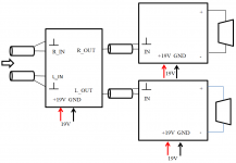
The Dahlia is built out of 2 modules:
The tube stage drives two current amplifiers. One for each channel L+R. The current amplifiers employ the dynamic bias circuitry.
So, the overal design is a standard tube-transisor hybrid; tubes for voltage amplification, transistors for current amplification.
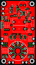
The attached schematic is the current amplifier.
TS3 is the impedance buffer. It is a bootstrapped emitter follower so that the driving tube sees a high impedance load. This emiitter follower loaded by a CCS around TS1/TS2.
The output stage is an Sziklai emitter follower (TS4/TS5). The CCS for this stage is built around TS6.
The dynamic bias current works as follows:
The current through the output Sziklai is measured over R11 by opamp IC1:1 and converted into a smaller current that is input to opamp IC1:2 and amplified. The maximum gate voltage for TS6 is set by IC2. TS7, C4 and R12 form a peak detector circuit.
Now, when no current is flowing through the Sziklai, the voltage out of IC1:2 will be equal to the voltage set by IC2 and the bias current through the output stage will be max. When enough current flows through the Sziklai the voltage out of IC1:2 will be reduced and the bias thus as well. Thanks to the peak detector bias can be ramped up quickly but will ramp down slowly. The time constant of the ramp down is set by C4/R12.
Next post will be the voltage amplifier.
The Dahlia is built out of 2 modules:
- Voltage amplifier
- Current amplifier
The tube stage drives two current amplifiers. One for each channel L+R. The current amplifiers employ the dynamic bias circuitry.
So, the overal design is a standard tube-transisor hybrid; tubes for voltage amplification, transistors for current amplification.
The attached schematic is the current amplifier.
TS3 is the impedance buffer. It is a bootstrapped emitter follower so that the driving tube sees a high impedance load. This emiitter follower loaded by a CCS around TS1/TS2.
The output stage is an Sziklai emitter follower (TS4/TS5). The CCS for this stage is built around TS6.
The dynamic bias current works as follows:
The current through the output Sziklai is measured over R11 by opamp IC1:1 and converted into a smaller current that is input to opamp IC1:2 and amplified. The maximum gate voltage for TS6 is set by IC2. TS7, C4 and R12 form a peak detector circuit.
Now, when no current is flowing through the Sziklai, the voltage out of IC1:2 will be equal to the voltage set by IC2 and the bias current through the output stage will be max. When enough current flows through the Sziklai the voltage out of IC1:2 will be reduced and the bias thus as well. Thanks to the peak detector bias can be ramped up quickly but will ramp down slowly. The time constant of the ramp down is set by C4/R12.
Next post will be the voltage amplifier
.Attachments
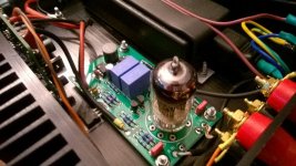
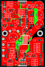
Tube stage
Here is the schematic of the tube stage. View attachment Voltage_amplifier.pdf
The tube stage itself is mu-follower circuit. I originally intended to use an ECC88 here but after some listening tests I actually ended up with an ECC81.
The current source for the tube mu-follower stage is built using two transistors. The tube is biased at about 2mA with 80V on the plates. The heater voltage is 12.6V (two heaters in series). The circuit can be adapted to use an ECC88 as well. In that case the heater voltage must be reduced to 6.3V (change R7/R8) and the cathode resistors must be changed to get 80V on the plates (R9/R17).
As the whole amplifier is intended to run from a 19V laptop adapter, the tube stage PCB also contains a DC/DC converter to generator the plate voltage. The DC/DC converter uses a jellybean MC34063 (or MC33063) switching regulator. As this regulator can only handle about 40V, TS1 is added to create a cascode circuit. The cascode limits the voltage on the switching pins to safe levels. The MC34063 is also running without any feedback. With feedback, it would skip pulses creating audible low-frequency noise. As it is now it runs at about 45Khz. Far away from the audio range of 20Hz..20kHz to cause any problems. The output voltage is limited by zener D3 to about 100V.
In the next post I will show the PCB layouts and how everything comes together.
Block diagram and PCB's
This is the final installment on Dahlia.
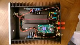
As said before, Dahlia consists of 3 modules (or actually 4 if you include the power supply):
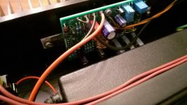
The PCB's are also shown, note that the current amplifier PCB's are designed to be mounted against a heatsink. The MJE3055 and the IRF9540 must be properly heatsinked as each can dissipate about 20W during peaks. Most of the time however, when quietly playing music, Dahlia will turn the bias down so that each power transistor only dissipates about 2W. I have measured the total power consumption of the amplifier at about 15W when idleing. This is actually quite a "green" amplifier The voltage PCB contains an LM317 that also needs to be cooled. I screwed this part to the metal bottom plate of the cabinet. Also, note that all of these parts need proper isolation and grease (mica, plastic washer and cooling grease).
So, what do you think of the design? I have spend quite some polishing this. The dynamic bias circuitry for example is a simple idea but to get it working properly is not easy. The same goes for the DC/DC converter. To get this to run without interfering with the audio signal is not simple.
Any comments? Anybody interested in building the design as well?
This is the final installment on Dahlia.
As said before, Dahlia consists of 3 modules (or actually 4 if you include the power supply):
- A stereo voltage amplifier
- A current amplifier for the left channel
- A current amplifier for the right channel.
- A 19V...19.5V laptop power supply of at least 90Watts
The PCB's are also shown, note that the current amplifier PCB's are designed to be mounted against a heatsink. The MJE3055 and the IRF9540 must be properly heatsinked as each can dissipate about 20W during peaks. Most of the time however, when quietly playing music, Dahlia will turn the bias down so that each power transistor only dissipates about 2W. I have measured the total power consumption of the amplifier at about 15W when idleing. This is actually quite a "green" amplifier
The voltage PCB contains an LM317 that also needs to be cooled. I screwed this part to the metal bottom plate of the cabinet. Also, note that all of these parts need proper isolation and grease (mica, plastic washer and cooling grease).So, what do you think of the design? I have spend quite some polishing this. The dynamic bias circuitry for example is a simple idea but to get it working properly is not easy. The same goes for the DC/DC converter. To get this to run without interfering with the audio signal is not simple.
Any comments? Anybody interested in building the design as well?
Attachments
Any comments? Anybody interested in building the design as well?
this is final version of my early started thoughts
unbelievable!
@Mathesar
Really interesting this design
Really interesting this design
Do not forget to give your impressions of the sound of this amplifier.Subscribed. Thanks for the nice design. I will build one too
BOM
Hi
I made the Bom's for Mouser during the weekend and would like to share them with you for those who want to build this amp:
Current AMP (you will need 2 of these)
Voltage AMP
I will receive the parts this week and start the construction as I already have the enclosure and the mechanical parts...
Best regards
Christoph
BOM Corrections
Hi
I discovered 3 mistakes in the BOM and corrected them
(wrong footprint for the potentiometer R18, wrong quantities for
the capacitors 0.1uF and 0.01uF on the voltage amplifier).
I soldered the voltage amplifier yesterday night. No issues at all.
Keeping you updated
Best regards
Christoph
Hi
I discovered 3 mistakes in the BOM and corrected them
(wrong footprint for the potentiometer R18, wrong quantities for
the capacitors 0.1uF and 0.01uF on the voltage amplifier).
I soldered the voltage amplifier yesterday night. No issues at all.
Keeping you updated
Best regards
Christoph
This is the final installment on Dahlia.
The same goes for the DC/DC converter. To get this to run without interfering with the audio signal is not simple.
Any comments? Anybody interested in building the design as well?
What about using capacitance multiplier (BJT or MOSFET) after switching DC/DC converter? That should reduce noise substantialy.
Also your tube voltage amplifier looks like grounded cathode amplifier with CCS load. It is not mu-follower.
What about using capacitance multiplier (BJT or MOSFET) after switching DC/DC converter? That should reduce noise substantialy.
Also your tube voltage amplifier looks like grounded cathode amplifier with CCS load. It is not mu-follower.
The simulated ripple coming out of the DC/DC converter is about 3mVPP (peak-peak). This ripple is purely comprised of dV/dt ripple caused by the charging and discharging of the reservoir capacitor. There is almost no ripple caused by the ESR of the reservoir capacitor because a foil cap has been used. (with a HV elco the ripple is about 100 times worse
, the first prototype showed that in practice .... ) However, because the tubes are indeed loaded by a CCS, this translates in a ripple current through the tubes of just 7nAPP.... very low...
But, in practice the ripple is a bit more. This is mainly caused by capacitive and inductive coupling into the tube and the traces of the PCB. Thus, a capacitance multiplier would not have improved the situation much.
I was always under the impression that a mu-follower is a CCS loaded common cathode stage....
. Whether the CCS is realized using a tube or a mosfet/bjt doesn't matter. With CCS loading, the PSRR, distortion and gain are all most optimal which is why I used it. In this circuit, the gain of the tube is equal to its specified mu, hence the name mu-follower.It is partially correct that mu-follower is a gain stage with amplification of close to mu but it is also characterised by the low output impedance from that of a cathode follower. CCS loaded grounded cathode Zout is roughly rp while cathode follower is 1/gm.
In your case it doesn't matter as the BJT buffer does the job of lowering Zout while the bootstrapped resistor keeps gain close to mu.
In your case it doesn't matter as the BJT buffer does the job of lowering Zout while the bootstrapped resistor keeps gain close to mu.
I have built the amplifier as well, I know the designer personally, a skilled man
The amplifier sounds really smooth, it has the character of a full tube amplifier. The output power is slightly too low for me. (That may also be because of my, well, inefficient speakers...)
If you would ask me whether you should build it or not, I would say give it a try! I built the amp mostly out of used (desoldered) components, it cost me about 25 euro's. It is very hard to beat the performance of this amp by a commercial amp (especially for the money).
I have built the amplifier as well, I know the designer personally, a skilled man
The amplifier sounds really smooth, it has the character of a full tube amplifier. The output power is slightly too low for me. (That may also be because of my, well, inefficient speakers...)
If you would ask me whether you should build it or not, I would say give it a try! I built the amp mostly out of used (desoldered) components, it cost me about 25 euro's. It is very hard to beat the performance of this amp by a commercial amp (especially for the money).
Hi Joris
Your amp sounds good
. I especially like the case .How are the other builders doing (Cgraph?). I hope you also like the sound of this little amp...
- Status
- This old topic is closed. If you want to reopen this topic, contact a moderator using the "Report Post" button.
- Home
- Amplifiers
- Solid State
- Dahlia hybrid amplifier