Hello all,
I can get a Bosch-Philips PA mono amplifier for cheap(~25$), but first I want to know a few things.
It seems it has an output transformer that offers 70V/100V/ and 8ohm outputs.
I can understand why they used an output transformer. But I would like to use this unit for a subwoofer that I have.
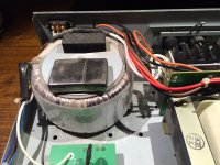
The unit has a rated output of 240W, giant toroidal transformer with a 34VDC output from the power supply. My subwoofer has 4 ohms impedance.
Now, I would like to remove the output transformer since I plan to use this for low frequency amplification. I don't think having the transformer at the output helps very much.
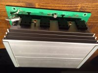
The output stage is in a push pull configuration and uses 4x2sc5200 per side.
I like the build quality of this thing, seems like a tank, proper power transformer (input power rated at 760VA) and good active cooling.
Any way I can transform this thing? Has anyone done this?
I could consider making another output stage using the same transistors and cooling system, for 200-300W system for the subwoofer.
I'm interested in 20-100Hz frequencies.
Any recommended schematics for 8 parallel 2sc5200?")
I can get a Bosch-Philips PA mono amplifier for cheap(~25$), but first I want to know a few things.
It seems it has an output transformer that offers 70V/100V/ and 8ohm outputs.
I can understand why they used an output transformer. But I would like to use this unit for a subwoofer that I have.
The unit has a rated output of 240W, giant toroidal transformer with a 34VDC output from the power supply. My subwoofer has 4 ohms impedance.
Now, I would like to remove the output transformer since I plan to use this for low frequency amplification. I don't think having the transformer at the output helps very much.
The output stage is in a push pull configuration and uses 4x2sc5200 per side.
I like the build quality of this thing, seems like a tank, proper power transformer (input power rated at 760VA) and good active cooling.
Any way I can transform this thing? Has anyone done this?
I could consider making another output stage using the same transistors and cooling system, for 200-300W system for the subwoofer.
I'm interested in 20-100Hz frequencies.
Any recommended schematics for 8 parallel 2sc5200?
Attachments
I'd pay $25 for that just for the heat sink. With a power transformer not smoked, $50.
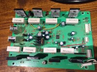
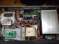
Appears to use a JRC4580 as a input buffer, not a shabby part. Peavey uses a lot of those. Two driver transistors on little heat sinks, one maybe voltage regulator in the middle? Not bad.
Appears to use a JRC4580 as a input buffer, not a shabby part. Peavey uses a lot of those. Two driver transistors on little heat sinks, one maybe voltage regulator in the middle? Not bad.
Last edited:
The power transformer outputs 26VAC RMS but it looks like it can deliver lots and lots of amps. Maybe a voltage multiplier?
The signal input PCB has another JRC 4558(same as the one on the main pcb). It's a preamp/gain stage. The one on the main PCB is a phase inverter/splitter.
If I remove the power supply pcb and the output transformer I have lots of room to make an adequate supply.
If the transformer outputs 26VAC RMS (under light load), and the input rating is 760VA, does that mean that the transformer can deliver 29A? If so, then it would be a shame not to use it for a sub amplifier
Zippo is for size reference.
Attachments
When you say 34V supply, do you mean +/-34V supply - in other words actually a 68V supply.
If so the amplifier, with the output transformer removed, will give you about 100W to a 4 ohm speaker.
Hopefully, it's not a single 34V supply, with the output stage operating push-pull into a center tapped output transformer. If so you are so screwed when it comes to removing it. PA amplifiers of yesteryear used to be built that way. I haven't seen a modern one built that way, but there is a first time for everything.
The power transformer outputs 26VAC RMS but it looks like it can deliver lots and lots of amps. Maybe a voltage multiplier?
Again, is it a single 26V, or is it 26-0-26?
If it's only a single winding then you're pretty stuffed, as it's presumably a very low output impedance amp relying on the transformer to increase the impedance.
Without the output transformer power will be abysmally low.
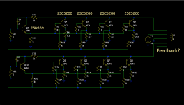
I tried to reverse engineer the schematic, but I could only do the power output. It gets complicated really fast after that.
There's a 24V regulator used for the op-amps, there's a Samsung IC for the Vu-Meter on the front panel, and two kinds of thermal protection, one starts the Fan and the other throttles down the output I think.
Anyway, the two output pairs that deal with each half of the sine-wave are identical, with opposite phase.
The board has a connector for the output, with 5 pins, that all go into the transformer. from 1-5 it's like this:
1- output from one phase
2- V+
3- GND
4 - the other output
5 - I think this is some kind of feedback. If I disconnect only this wire, the whole signal becomes almost a square-wave. Don't know what this is.
I measure the resistance and I think the connection is like this:
O1~~~V+~~~O2
Feedback?~~~~GND
There's no reading between these two pairs of connections.
I did measure the signal after the op-amp and indeed it's the phase inverter.
Attachments
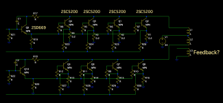
I drew the connections to the transformer as I think they are.
I don't know where that feedback link is coming from, I didn't have the patience to trace it, but I did see that among other components, it also went into the vu-meter IC, but for sure that is not it's only function.
I don't know where that feedback link is coming from, I didn't have the patience to trace it, but I did see that among other components, it also went into the vu-meter IC, but for sure that is not it's only function.
Attachments
Hi,
No-one is considering the power amplifier may be bridged.
I'm saying it must be, if the power supply is single rail.
Not at all, as it's transformer output there's no requirement for bridging at all - and even assuming it was bridged, that's still no where near it's rated power without a low to high impedance output transformer (assuming bridging, and a 4 ohm load, you'd only get about 100W or so).
Certainly the output diagram the OP has posted shows no indication it might be bridged.
I'm with indianajo, it's worth $25 just for the heatsink
Ok, so that's settled then.
But now, can I use a voltage doubler circuit for the intended application?
300W subwoofer amplifier into 4 ohms? Voltage doubler at minimum, maybe triple the voltage?
Would such a circuit be ok for this thing? I feel really bad not to be able to use the nice transformer, I bet it's built very good.
Also I'll need a nice circuit around these transistors.
The output transformer may be more useful. Turn it around and run 120V AC into the 100V "output" and get +/-36-ish VDC from the other side, good for at least 240VA. A light bulb limiter will tell you if the tranny can take that little bit of overvoltage - my guess is that it can if the amp was designed for low distortion down to 50-60 Hz. Bridge THAT and you'll be getting somewhere.
A voltage doubler circuit, even on that toroid, would have **** poor regulation and a ridiculous amount or ripple.
A voltage doubler circuit, even on that toroid, would have **** poor regulation and a ridiculous amount or ripple.
Never done it, and don't know
Actually I did make the toroids needed for the TA2020 amp, using the recommended core, but those were small.
I was thinking about rewinding right now, I might have a look at the theory just to understand if it's doable or not.
I presume the secondary is wrapped around the primary?
Actually I did make the toroids needed for the TA2020 amp, using the recommended core, but those were small.
I was thinking about rewinding right now, I might have a look at the theory just to understand if it's doable or not.
I presume the secondary is wrapped around the primary?
What output voltage should I aim for?
Depends on how many watts and how many ohms. 50-0-50 AC would be nice useful amount of power (at least 400 watts in 4 ohms).
Ok, so that's settled then.
But now, can I use a voltage doubler circuit for the intended application?
Doublers and triplers are basically low power circuits, while I suppose it's theoretically possible it would cost more than buying a new transformer.
300W subwoofer amplifier into 4 ohms? Voltage doubler at minimum, maybe triple the voltage?
Would such a circuit be ok for this thing? I feel really bad not to be able to use the nice transformer, I bet it's built very good.
Doesn't matter how well it's built, it's useless unless you have a use for it - and it's a pretty unusual specification. Incidentally, I've had a transformer over 40 years - a friend and I bought it because we couldn't get the voltage we wanted, and thought we could 'improvise' using the one we got. 40+ years on, it's still never been used
But regardless, you're looking at a complete rebuild of the amp, including the PSU - is it worth it?.
Why can't you just use the amp with the output transformer?, doesn't it have a 4 ohm output?, if not get yourself a new 8 ohm subwoofer.
- Status
- This old topic is closed. If you want to reopen this topic, contact a moderator using the "Report Post" button.
- Home
- Amplifiers
- Solid State
- PA mono amplifier, want to remove output transformer