Specifically applying to a Quad 306 output stage, what are the advantages or disadvantages of increasing the Vf of the diodes. D5 - D10, ?
The 306 standard is supplied with 1N4003, with Vf max of 1.1v , would UF 4007
Vf of 1.7v with different forward characteristic namely rising Vf with current be advantageous, or disadvantageous
https://www.fairchildsemi.com/datasheets/UF/UF4001.pdf
Thank you / Chris
The 306 standard is supplied with 1N4003, with Vf max of 1.1v , would UF 4007
Vf of 1.7v with different forward characteristic namely rising Vf with current be advantageous, or disadvantageous
https://www.fairchildsemi.com/datasheets/UF/UF4001.pdf
Thank you / Chris
Attachments
I can't see the point of changing the biasing and catch diodes for ultra fast types. These are not used as power rectifier diodes, where some like to use UF and Schottky types, providing there is adequate RFI/EMI shielding and filtering to prevent pollution of the rail supplies. That is the penalty for using power devices that are too fast in audio circuits.
Biasing and bridge balance could change if Vf was significantly different but the Vf variation at 25C for a current range of 0.1-1A is 0.6-0.8V for both IN4003 and UF4003 so with the appropriate diode choice, this is probably not an issue. http://www.onsemi.com/pub_link/Collateral/1N4001-D.PDF
Biasing and bridge balance could change if Vf was significantly different but the Vf variation at 25C for a current range of 0.1-1A is 0.6-0.8V for both IN4003 and UF4003 so with the appropriate diode choice, this is probably not an issue. http://www.onsemi.com/pub_link/Collateral/1N4001-D.PDF
Last edited:
I can't see the point of changing the biasing and catch diodes for ultra fast types. These are not used as power rectifier diodes, where some like to use UF and Schottky types, providing there is adequate RFI/EMI shielding and filtering to prevent pollution of the rail supplies. That is the penalty for using power devices that are too fast in audio circuits.
Biasing and bridge balance could change if Vf was significantly different but the Vf variation at 25C for a current range of 0.1-1A is 0.6-0.8V for both IN4003 and UF4003 so with the appropriate diode choice, this is probably not an issue. http://www.onsemi.com/pub_link/Collateral/1N4001-D.PDF
Thanks Ian.
The Quad amp described is a 'current dump' virtual earth amplifier and it will not improve matters to muck about changing components.
Disagree, as there is imbalance in the bridge with standard components namely
R24 and R25 , plus early to later models corrected R35 providing it in
later editions and when serviced by themselves to be the same as a Quad 606. A 909 correcting this 10k resistor further to the junction of L1
Cheers / Chris
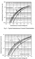
Within a diode family (i.e. 1N400X, 1N540x, UF400x) the higher voltage diodes (400PIV up) have a larger spaced junction, different doping and thus higher forward voltage, slower switching, but this also means the slope of the forward voltage curve is flatter. See graphs Vishay UF4001-4007 family. SPICE models for On-Semi 1N4001 and On-Semi 1N4007
Ideally the slope tracks the O/P transistors, I guessing that's what you want to optimize? I don't know the Quad circuit, but would SPICE model the old and new to see the trend.
Ideally the slope tracks the O/P transistors, I guessing that's what you want to optimize? I don't know the Quad circuit, but would SPICE model the old and new to see the trend.
Attachments
Within a diode family (i.e. 1N400X, 1N540x, UF400x) the higher voltage diodes (400PIV up) have a larger spaced junction, different doping and thus higher forward voltage, slower switching, but this also means the slope of the forward voltage curve is flatter. See graphs Vishay UF4001-4007 family. SPICE models for On-Semi 1N4001 and On-Semi 1N4007
Ideally the slope tracks the O/P transistors, I guessing that's what you want to optimize? I don't know the Quad circuit, but would SPICE model the old and new to see the trend.
Yes you are on to it nicely, namely the slope of the diode better tracking the 0/P transistors.
Yes the ideal bias diode has identical change in I/Vbe per degree of junction temperature change as the Transistor it's biasing. How the Vf affects this, should be the question.
Thank you for defining how this is versed, that is a big help
Cheers / Chris
I think you have this "the slope of the forward voltage curve is flatter" back to front.Within a diode family (i.e. 1N400X, 1N540x, UF400x) the higher voltage diodes (400PIV up) have a larger spaced junction, different doping and thus higher forward voltage, slower switching, but this also means the slope of the forward voltage curve is flatter. See graphs Vishay UF4001-4007 family. SPICE models for On-Semi 1N4001 and On-Semi 1N4007
Ideally the slope tracks the O/P transistors,............
Look at the two 25°C curves for 0.01A to 0.1A
The low voltage diodes (upper) shows ~0.60Vf to ~0.72Vf (a difference of ~120mVf)
The high voltage diodes (lower) shows ~0.6Vf to ~0.85Vf (a difference of ~250mVf)
For the same range of current the high voltage diodes have roughly twice the delta Vf.
This to me means that the low voltage diodes have the "flatter" slope of the voltage curve. i.e the voltage changes less with a change in current.
looking at the 0.1A to 1A range confirms similar voltage changes: LV diodes 230mV (0.95-0.72) and for HV diodes 540mV (1.39-0.85)
You can repeat the exercise for other temperatures. But I suspect you will find that the LV diodes have the flatter slope.
Last edited:
I think perhaps prairiemystic was just describing the curve as being closer to horizontal - hence flatter in that respect.I think you have this "the slope of the forward voltage curve is flatter" back to front....
That would be the current slope is flatter with respect to Vf.
But that is not the way we generally specify "slope".
cf. Zener diode and LED and voltage Regulator.
For these we look at the slope of the voltage curve as the current is changed.
A flatter slope implies that the voltage does not change much for big changes in current.
But that is not the way we generally specify "slope".
cf. Zener diode and LED and voltage Regulator.
For these we look at the slope of the voltage curve as the current is changed.
A flatter slope implies that the voltage does not change much for big changes in current.
I calculated the slope using two-point rise/run dI/dV and get:
UF4001-4: 0.72V@0.1A and 0.6V@0.01A = 0.75mA/mV
UF4005-7: 0.85V@0.1A and 0.6V@0.01A = 0.36mA/mV
I call the lesser slope "flatter", I guess it's perspective.
But shouldn't we be comparing temperature shift too. Assuming bias duty at 0.01A from 25°-100°C the curves look the same. So an offset shift is the main difference? I'd still use SPICE.
- Status
- This old topic is closed. If you want to reopen this topic, contact a moderator using the "Report Post" button.
- Home
- Amplifiers
- Solid State
- Advantages or Disadvantages in increasing Vf of Bias Diodes