Thanks for doing that Mooly, totally forgot to put the darlington in there. Boy were the values I was getting wrong by using the tutorial links that I posted.
So I'm getting the feeling so far that there is no online resource that explains how to get the R values for this circuit. What book do I need to get then? Douglas Self's?
Maybe there isn't much around because its not really a good example that would ever be used.
First look at how 'low' the darlington can pull that 3 ohm resistor toward ground. If we turn it fully on, it can still only get to within a volt or so of ground because of the massive collector current flowing. That's because the transistor isn't 'perfect'.
Why do we need such a massive current ? Well look at the load resistance you want to drive. Eight ohms ! The collector load resistor (3 ohms in my example) means that this 3 ohms always appears 'in series' with the load. If we increase the 3 ohms to make things easier for the transistor then the available voltage swing left for the load falls dramatically. The base bias network also needs to be low in value because even though the transistor is a darlington, it still needs significant base current to bias the transistor to the correct DC operating point (to around half supply voltage on the collector) so that the stage can swing equally above and below a nominal point. In the simulation, the bias network isn't really low enough and even removing the 1500 ohm still allows the stage to operate. You would think the 10k feeding the base of a darlington would just saturate the transistor but in the sim it doesn't. Actually that makes sense because the collector volts has fallen so low that there is little available to provide the current required.
So all in all its not a great design... but you could look at making a discrete darlington and returning the first transistor collector to the supply... or using a power FET.
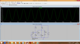
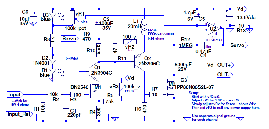
Just to be picky and contrary - you could, with an inductor-fed single ended amp. Not real easy, but feasible. I have one that does a clean 8W into 4 ohms from a 13.6V supply. Pretty sure I could get to 5W at 8 ohms with the additional 1.4VDC...
I first saw that trick done in an Elektor PA amp many many years ago. Geez, it was a long time ago too......
(Was it called the Stentor ?)
I know, that IS my problem! I won't learn anything by building any project
that someone simply hands me numbers for. I'm looking for a guide to
calculate what values things should be like the links I posted in the OP
except something that is useful. I'm not asking anyone to do the work
for me, I just can't find the information online to learn from so don't
get all pi$$y about it.
Hi,
Your not looking in the right places.
Like I said you can find out online how to analyse a one transistor circuit.
Just don't expect the numbers to reflect an ill-advised power amplifier.
The analysis is pretty straightforward and should be covered
well enough in any decent textbook or online design resource.
Look at line stages, noting they will quickly move on to multiple
devices, due to the serious limitations of a single device stage.
rgds, sreten.
I first saw that trick done in an Elektor PA amp many many years ago. Geez, it was a long time ago too......
(Was it called the Stentor ?)
Back in the mid/late 60s it was the standard way of doing Delco car radio outputs, using a bolt mount pnp germanium output transistor. Needs just half the heatsink (but the inductor can be as expensive as, and a lot heavier than the heatsink). Theoretically the same efficiency as push-pull, but can't transition to class AB like p-p can.
Quite a few years ago (maybe 8 to 9) there was a Thread showing an Inductor fed single ended amplifier.Lol.
The ones in LT live forever. Its an interesting concept. Bigger inductor... more power... more power... more voltage
It claimed good efficiency.
Yes, you can get up to a theoretical 50%. I achieved 35% with 42W output and 120W dissipation on the mosfet. A beautiful harmonic profile, sounded wonderful. Hint: The Pass Zen is worth a good look; uses a mosfet in common source and does up to 10W. Very good sound quality but horrific heat output, need a fan.
Hugh
Hugh
OK Abrax, 4 ohms and no bridged.
My working towards a design goes like this.
Let's assume the transistors involved can swing to 1V from the rail. That gives us a peak output voltage of 6.5V from the 15V rail. 6.5V across 4ohms gives just over 1.5A, let's conservatively say 2A because the speaker might dip below 4ohms.
The current source must be able to supply the full output current when the EF is practically cut-off, so we need a constant current source biassed to give 2A. The EF needs to swing up to 4A at the opposite extreme - to absorb 2A from the CCS and also provide 2A to the load.
At quiescent with 7.5V on the output the two power transistors are dissipating 15W each. The peak power to the load is 10W, 5W average with a sinewave playing.
Are you still wedded to your darlington as the power transistor of choice? If so I'll have to take some time out to work out how to design a CCS with a darlington as the active element, something I've not tried before.
Sounds like this was a stupid idea to use a darlington for class a. I was just trying to pick something simple to get my feet wet but clearly I'm in over my head. I don't want a zen amp. After all the work it would be an expensive space heater with low power output and I wouldn't gain any understanding in single stage design.
Can anyone recommend a project for a simple class A or AB low power amp project that breaks down how to decide component values?
Might I suggest this (brilliant, amazing, different, weird, maybe stupid) design?
http://www.diyaudio.com/forums/solid-state/276375-single-ended-class-no-global-feedback-8w-mosfet-low-output-z.html
Or a higher-power variation of it, soon to be published in an upcoming issue of Linear Audio..
http://www.diyaudio.com/forums/solid-state/276375-single-ended-class-no-global-feedback-8w-mosfet-low-output-z.html
Or a higher-power variation of it, soon to be published in an upcoming issue of Linear Audio..
Last edited:
Might I suggest this (brilliant, amazing, different, weird, maybe stupid) design?
http://www.diyaudio.com/forums/solid-state/276375-single-ended-class-no-global-feedback-8w-mosfet-low-output-z.html
Or a higher-power variation of it, soon to be published in an upcoming issue of Linear Audio..
Yes it is weird all the waY
20mH it`s small inductance even for 8 Ohm speakers. Servo for a cap coupled output? etc...I`ve made something similar few years ago, but with GNFB. It sounded very good, it could be improved, but I moved on from it...
http://www.diyaudio.com/forums/solid-state/226296-thetwelve-se-class-tmc-amplifier.html
Something that I just read in an interview with N. Pass here: Nelson Pass Interview - Audiophile Review
"In 1975 the Threshold 800A was a five-stage amplifier sporting a triple series / triple parallel / triple Darlington output stage and a dynamic bias circuit. By 1998 the Pass X1000 delivered a high quality kilowatt with only two stages. Currently I have a couple of amplifier projects with only one transistor."
Any idea what project he might be referring to here with 1 trans?
Yes it is weird all the waY
The design was actually for 4 ohms and used to drive a speaker from 70Hz up. Surprisingly, the bass is maybe the best subjective characteristic, very strong yet tight sounding.
The servo contols idle currnent, via an otherwise not very relevant dc output voltage (note that the drain of the output fet idles very near the supply rail, dc bias equals dc voltage across the inductor resistance).
So, yes, weird, but also one of my favorite amps. The other is its newer variation.
Last edited:
- Status
- This old topic is closed. If you want to reopen this topic, contact a moderator using the "Report Post" button.
- Home
- Amplifiers
- Solid State
- Single stage class A calculations...