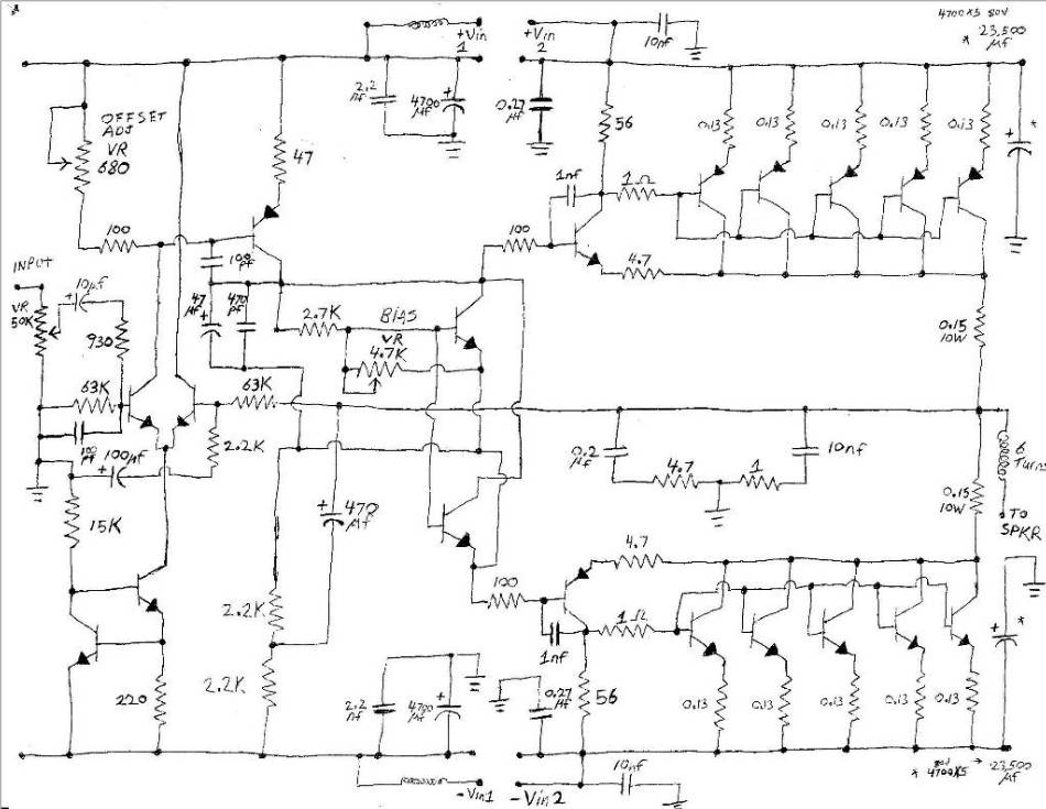
Came across this topology just now. Never seen it before. The idea is that with a normal complementary output stage the NPN and PNP transistor characteristics might not be exact opposites. With this "super complementary" topology though, the upper and lower transistor characteristics are the parallel sum of the each transistor pair. so the upper and lower end up being more or less exactly equal.
Is this circuit in widespread use?
Is it worth a closer look or just no big deal?
Is this circuit in widespread use?
Is it worth a closer look or just no big deal?
Attachments

Hi Circlotron,
you may be interested by the Bryston output stages.
Google "bryston amplifier schematics".
Here's one :
Bryston 3B~8B Power Amplifier Schematic Diagram | Free eBook Download
you may be interested by the Bryston output stages.
Google "bryston amplifier schematics".
Here's one :
Bryston 3B~8B Power Amplifier Schematic Diagram | Free eBook Download
Forum member Lazy Cat did something like that only using a MOSFET as the driver. As already mentioned, Bryston has been doing similarly for years.
Setting R1=R2 is equivalent to assuming that PNP_Q2_Beta=NPN_Q3_Beta. If the betas are not equal then whichever transistor has the higher beta, does most of the work.
Took about 15 minutes to find it.Forum member Lazy Cat did something like that only using a MOSFET as the driver. As already mentioned, Bryston has been doing similarly for years.
http://www.diyaudio.com/forums/solid-state/234630-super-complementary-output-stage.html
Looks like he got the idea from the same site as me.
Edit -> ^^ wrong thread.
Can't find Lazy Cat's one.
Last edited:
That is quite true, but the end result is work done by Q2 + Q3 added together. If it is the same as the bottom pair of transistors then all should be well. In any case, with a conventional topology Q2 and Q3 might be on opposite sides so you problem would presumably be worse.Setting R1=R2 is equivalent to assuming that PNP_Q2_Beta=NPN_Q3_Beta. If the betas are not equal then whichever transistor has the higher beta, does most of the work.
That is quite true, but the end result is work done by Q2 + Q3 added together. If it is the same as the bottom pair of transistors then all should be well
Then you can save yourself a non-negligible amount of money. If the numerical value of the ratio (NPNbeta/PNPbeta) is unimportant, then save some money by setting the NPNbeta equal to zero: completely remove Q3 and Q7. You will still have (Q2 + Q3) matching (Q6 + Q7); and as post #1 says, "the upper and lower end up being more or less exactly equal."
"Edit -> ^^ wrong thread.
Can't find Lazy Cat's one. "
http://www.diyaudio.com/forums/solid-state/193923-simple-symetrical-amplifier-304.html#post3163129
Can't find Lazy Cat's one. "
http://www.diyaudio.com/forums/solid-state/193923-simple-symetrical-amplifier-304.html#post3163129
Seems like the simple CFP that has internal gain will serve just as well.
Also, according to Self, you cannot parallel more transistors in CFP output stage as distortion increases unlike the simple EF stage. If this is similar to CFP, you are limited to single output pair.
A simple EF with multiple output pairs might be superior. Particularly if it is a folded 3EF, the Vbe variation due to variation of current of the pre-driver and the driver partially cancels out.
Last edited:
US2002005759 Ultra complementary audio amplifier output stage
The Ultra Complementary Output Stage utilises both direct and bootstrapped drive for the output power devices in audio frequency power amplifiers operating in Class A, Class AB or Class B, in emitter follower, Sziklai pair/hybrid, or compound (eg. triple) configurations.
Attachments

I'm running a paralleled set of CFPs, with no issues nor distortion increase (according to SPICE). You have to have a separate "input" transistor for each (i.e., parallel CFPs, not just the power devices). And remember that the thermally sensitive device in a CFP is the small input transistor (not the big power device) so have the input transistors thermally coupled together.
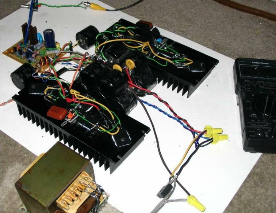
I built a CFP 5X parallel amp years ago here, back when I was a newbie, ended up pushing 600W @ 2 ohms, double the planned output, and worked FLAWLESSLY, until it was lost in an arson.
HERE IS THE THREAD http://www.diyaudio.com/forums/solid-state/61542-questions-building-high-powered-subwoofer-amp.html
CLICK THE THREAD TO SEE FULLSIZE PICS, ONLY THUMBNAILS ARE SHOWING HERE
HERE IS THE THREAD http://www.diyaudio.com/forums/solid-state/61542-questions-building-high-powered-subwoofer-amp.html
CLICK THE THREAD TO SEE FULLSIZE PICS, ONLY THUMBNAILS ARE SHOWING HERE
Member
Joined 2009
Paid Member
Also, according to Self, you cannot parallel more transistors in CFP output stage as distortion increases unlike the simple EF stage. If this is similar to CFP, you are limited to single output pair.
A simple EF with multiple output pairs might be superior. Particularly if it is a folded 3EF, the Vbe variation due to variation of current of the pre-driver and the driver partially cancels out.
There are challenges paralleling CFPs (ask Sakis). But, better yet, use a CFP - Class AB-C output where you can add as much grunt as you want with MOSFETs whilst retaining a single BJT CFP output at normal listening levels.
http://www.diyaudio.com/forums/solid-state/245619-tgm8-amplifier-based-rod-elliot-p3a.html
- Status
- Not open for further replies.
- Home
- Amplifiers
- Solid State
- "super complementary" topology