After a long search I finally acquired a Sansui TU-X1 supertuner. I then discovered it doesn't fit in my stereo setup. Waaaay to big. But I digress. I fixed the AM demodulator (LM1496) and replaced the broken tiny bulbs in the output selector switches with white, even smaller 0603 LEDs on a 5x5mm piece of PCB. Now it works OK. The AM section needs work, FM works very well. The PSU caps are all perfect and do not need replacement. Maybe the output opamps do. I think they're weird and I don't trust them. I'd like to replace them with something more sensible like the venerable NE5534. Need to test first before condemning them.
Some things keep nagging me. The combined AM/FM input causes issues. Most important is that the shielding of the FM input is really poor. This picks up interference from equipment (LG LCD TV!) nearby. So this has to go and get changed into a proper, well shielded input with a BNC connector. Also the signal level indicator sucks. This is from a consumer FM IF chip and is not well calibrated. There are good solutions for this.
The AM, while still needing work, disappoints. The SSB demodulator aka beat canceler works very well but the IF narrow setting only switches in an audio low-pass filter and not a narrower IF filter like in the FM section. This definitely needs some serious modding which I don't think anyone has done before.
I'm not really looking for a solution but input would be highly appreciated. So, my question in this would be: how far can I go in modding this beast? Is what I want to do worse or better than just replacing all caps in the PSU and lobbing blobs of solder at all joints? I have plenty of experience and test equipment to successfully pull anything off but right now I'm kinda stuck...
I intend to do a write-up on my modding adventures, like I did on my vintage TVs.
Well you are one of a very few owners, so good luck.
without looking I guess they use Mitsubishi opamps, probably in the sip pkg too")
Things like the sig meter, does it really matter? I assume they used the ha1137 or ha12412.
I know that the sig meter works great on my Si4735 tuner
Wish I could help you cheers
without looking I guess they use Mitsubishi opamps, probably in the sip pkg too
Things like the sig meter, does it really matter? I assume they used the ha1137 or ha12412.
I know that the sig meter works great on my Si4735 tuner
Wish I could help you cheers
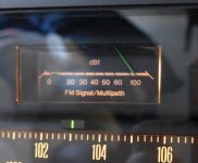
Thanks! You have a point about the signal level meter. It's driven from a humble HA1137W. What doesn't help is the scale of the meter itself. Not exactly a linear dB scale:
0 -- 20 30 40 50 60 - 100 [dBf]

(image shamelessly stolen from Tubejack.nl's website)
What also doesn't help is that the gain of the front end varies by no less than 18 dB. This is so much that it renders any indication useless. Come to think of it, this is an issue that should be solved first. Test it again, but now with the AGC circuit disabled. Yes, this is a complicated machine!
0 -- 20 30 40 50 60 - 100 [dBf]
(image shamelessly stolen from Tubejack.nl's website)
What also doesn't help is that the gain of the front end varies by no less than 18 dB. This is so much that it renders any indication useless. Come to think of it, this is an issue that should be solved first. Test it again, but now with the AGC circuit disabled. Yes, this is a complicated machine!
Attachments
Last edited:
Semi off topic: please be aware that DAB+ is the new standard. If you haven't noticed already: transmitting power of FM transmitters has already been reduced. It is not a question of DAB+ being better or worse than FM. FM will be phased out and it is currently in that process. For this reason I sold all my FM equipment. Better now than when they're completely unusable. I noticed mediocre FM reception when driving through the Netherlands. As opposed to earlier years I noticed noisy FM reception at many places while using an excellent car radio. After some research I was told transmitting power had been reduced.
DAB+ is not better than FM (soundwise) as they use lower bit rates than is possible. DAB+ is more convenient, no reception problems and transmitters use only 10% of the power of FM transmitters. The rollout progresses steady and coverage is good in most places. I tried quite a few DAB+ tuners and liked the Onkyo T-4030.
DAB+ is not better than FM (soundwise) as they use lower bit rates than is possible. DAB+ is more convenient, no reception problems and transmitters use only 10% of the power of FM transmitters. The rollout progresses steady and coverage is good in most places. I tried quite a few DAB+ tuners and liked the Onkyo T-4030.
Last edited:
I'm not interested in DAB. I get my digital fix online.
Like FM, AM is also on its way out. My Sansui has an AM section that puts many a DAB tuner to shame. And besides, what's the fun of listening to radio from a plastic box with some silicon chippery inside as opposed to a 16 kg beast with almost exclusively discretes in it?
Like FM, AM is also on its way out. My Sansui has an AM section that puts many a DAB tuner to shame. And besides, what's the fun of listening to radio from a plastic box with some silicon chippery inside as opposed to a 16 kg beast with almost exclusively discretes in it?
Honestly, I prefer the 99 Euro plastic DAB+ box because it works. A 16 kg beast that will be obsolete has no use in my home. Discrete, tubes etc.....it doesn't matter as the source will dry up.
DAB was bad, DAB+ is OK. I see many new cars have DAB+ tuners fitted. I guess we will have to live with it, it is here to stay
DAB was bad, DAB+ is OK. I see many new cars have DAB+ tuners fitted. I guess we will have to live with it, it is here to stay
Last edited:
We have no DAB in Canada, we are lucky to have the whole FM band almost filled with many excellent stations in my locale. There is HD-FM (IBOC) in the US that I have not evaluated.
For the rf agc, the agc signal is diode detected from the first IF stage(tr02) and the signal is level shifted and applied to the 2nd gate(s) of the mosfet, FET02. This can be disabled with mods, to allow the 2nd rf amp to run full gain, or other fixed gains, by tying them to a fixed or variable control V, around the 0-10V Vgs range IIRC (lower Vgs means less gain). Have to look at the 3sk41(NEC) spec's to be sure but lower grade units usually did not have rf agc and fixed biased the G2 of the rf mosfets. So it seems higher Vgs2 will give a lower agc gain.
To get a calibrated sig meter, it will be a challenge for sure, esp when you have RF AGC involved!
BTW, Yahoo groups has a FM tuner forum with more folks having high end tuner experience!!
I wonder how the TU-X1 compares to your other tuners?
Last edited:
I have no spec for it except for the blurb in the TU-X1 manual:

Pin #11 and tab are VEE and Pin #1 is VCC. I dunno wozzup with the Muting block. It seems to be used in the Dolby output which no one uses anyway. Sometimes I have no idea what the Japanese engineers were smoking at the time.
I'll have a go at that Yahoo group. As for the other tuners, it's hard to do a proper comparison. Quality of recovered audio (FM) is very good. I plan to have a shootout with a Revox B760 of a good friend but have to fix my antenna situation (3 el yagi) before we can do that. As for AM, I'm planning to string some wire over the roof of the apartment building I live in and hook up an autotransformer with a coax output to it. Hopefully it sits above the noise cloud and I can pick up stations from across the Atlantic. With all AM powerhouses being switched off in Europe there might be a good chance during those freezing winter nights when the D-layer is properly destroyed...
Attachments
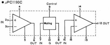
Ya that is about all i could figure on uPC1190C too. With that power tab, must be able to drive low Z, wonder if it was designed to drive headphones too?
As far as testing goes, what are you able to test on the au-x1? FM sig gen/mpx gen?
yes antenna's are very important. Having a good antenna with a rotor is ideal. I am lucky, i bought the house with a 50 ft tower, amp and rotor. Just replaced the rotor too. It is a deep fringe LPA, seems to work fine with 300 ohm balanced, I am far enough away from strong transmitters.
I bought an old Crown fm1 for $50, to play with as the GI controller is dead. Got it going using a multi-turn pot to control the varactors tuning V. Tested it against my Si4735D60 design.
One test that proves a good tuner is to have two adjacent carriers that are stronger than the station you are attempting to receive. The Si4735 is much better than any of the other tuners I have, in this regard. But then again i do not have a AU-X1 or a Revox to compare against
Last edited:
I can test pretty much everything. I lack a wobbulator or network analyzer, so I'd have to manually verify transmission (of filters etc.) with my signal generator and spectrum analyzer.
This Si4735 chip is pretty impressive. Especially with its tiny footprint (3x3 mm). Did you develop a PCB for that?!?
In the meantime, Yahoo isn't cooperating. It wants me to set up a profile (that I already have) and then refuses access to the FM tuners group because it's unaware of that fact. Or something. Ah well, maybe later. Or never.
I have a HP 8656B and recently got the guts of a HP 11715 cal gen to play with. i need to build/get a good mpx unit going one day.
yes i am impressed with the Si4735. I did a pcb up for it using a bunch of parts. Based it and the code on the Elektor DSP radio article. the RD(B)S features are nice to have and of course favourite stations, remote control ... etc
Search for Si4735 and my handle, I posted picks of the portable radio/media player on this site.
A chap on the MCS electronics site, re-wrote the code for the DSP radio, added many RDS enhancements, upgraded to mega328. he ran out of space on the m328 even. I intern re-wrote his code to run on my xmega design(s). Wonderful stuff to play with.
I guess this winter I'll roll the Si4770 design and try out an external DACs as I am sure it will improve the sound quality rather than to use the internal DACs.
I am not a fan of the yahoo groups web site either.
Last edited:
The portable media player pic is in this thread
http://www.diyaudio.com/forums/solid-state/233287-looking-complete-diy-amp.html#post3439666
http://www.diyaudio.com/forums/solid-state/233287-looking-complete-diy-amp.html#post3439666
"Wow" is praise enough for me. I certainly do not want to take too much credit as it really belongs to the chip and s/w designers.
I really would like to get as many as possible into the hands of FM radio and DIY fans and would be great if I could get some help in the radio user interface. Upgrading to a graphic LCD would be a nice enhancement.
But this thread is about the TU-X1, so lets continue on that subject. I really think that you should just enjoy the beast and not be too concerned about mod's, unless there is a reliability/performance problem, which sounds unlikely. For some things, it is better too leave as stock.
We have no DAB in Canada, we are lucky to have the whole FM band almost filled with many excellent stations in my locale.
Wow, you are a lucky one , here in Toronto I only know one.
I guess I don't want to touch the FM too much, except for the gain variation. I'll prolly leave the signal strength indicator as is. The AM is a different story. I really want to use this tuner as a DX device which means that it really really should have switchable bandwidth for AM.
Switchable "AM" B/W control should be fun. I guess one could look at other AM tuners having this feature(not too many of them however) and see how they accomplish this.
Usually xtal filters are used for low b/w, hi Q type IF filters. I know little of where to obtain them these days. I recall from my Motorola VHF/UHF radio days, they used 21.4MHz xtal IF filters in dual conversion type designs. I would have to look further in that subject matter.
Now that I look at the TU-X1 AM schematic, I am confused, wow a lot of circuitry. Would have to read up a bit more on its operation principles to offer any really advise. Gee almost as complicated as the Si4735
Sorry to say, this is where a DSP shines in BW filtering settings/features and noise reduction techniques.
Good luck none the less.
Hehheh- that Silicon Labs chippie is waaaaay more complicated than the TU-X1! But because it's concentrated into a fleck of silicon you don't see that. As for bandwidth switching: at FM they use an amp that gets switched in and out of the circuit. The AM section is differently: there's a direct connection from mixer (LM1496) to the filter and then a gain stage. The filter seems high impedance but is loaded with 330 ohm. Standard IF filters for 455 kHz are usually 3.3k. This will destroy the filter's performance. I'm thinking of a buffer stage after the mixer, then the narrow filter and a second gain stage that gets switched on and off as needed. Isolate the outputs with diodes to prevent transistor latch up. This would neatly solve the loading of the first filter.
As for the filter, an SSB filter with 3 kHz -3 (-6) dB bandwidth looks like a good choice. This will make the beat canceler circuit shine but operation will become a tad complicated...
I now also have the balun for the wire antenna. Now find a good spot to place it!
As for the filter, an SSB filter with 3 kHz -3 (-6) dB bandwidth looks like a good choice. This will make the beat canceler circuit shine but operation will become a tad complicated...
I now also have the balun for the wire antenna. Now find a good spot to place it!
- Status
- This old topic is closed. If you want to reopen this topic, contact a moderator using the "Report Post" button.
- Home
- Amplifiers
- Solid State
- Sansui TU-X1 Modding