Two questionsthis is my way to bias a powerstage (no difference for transistors or fets).
see attachment.
greet marius

What is the use of the opa in the circle?
And why a supply of ±15V to manipulate an input of not even 1V an an output of only a few volts
Mona
Attachments
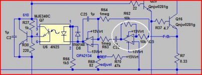
It won't work well in practice: the voltage across R7 is basically a half-wave rectified version of the output current, meaning the average value is signal-dependent.this is my way to bias a powerstage (no difference for transistors or fets).
see attachment.
greet marius
The quiescent current will wander wildly with the signal, and this will create lots of problems with real music.
You can probably adjust it for a fixed-amplitude, continuous tone, but other than that, it won't be very usable.
Try to simulate it with tone bursts, I think this will be revealing.
I have described an opto-bias sometime ago, you could take some ideas there. It hasn't been tested in reality, but it survives basic sim tests.
The AC component of the signal is not what I am concerned about here (it might be a problem in a second instance, but that's another issue): the second opamp compares the average value of the emitter current to a reference, and regulates it. That's where the crux of the problem sits.hoi Elvee please look again the first opamp gets rid off the ac component in the feedback signal.
Try simulating it in realistic conditions, you will probably see that things don't really work out nicely. That is a recurrent problem with many sliding bias schemes: Visch comes to mind, even though it doesn't rely on opto's.
Hoi Vandenberg,
Your proposal did me think of following schematic: have a look at the pdf "JC1 out".
http://www.diyaudio.com/forums/loun...ch-preamplifier-part-ii-4642.html#post3766093
Your proposal did me think of following schematic: have a look at the pdf "JC1 out".
http://www.diyaudio.com/forums/loun...ch-preamplifier-part-ii-4642.html#post3766093
We had a lot of discussion on this topic and http://www.diyaudio.com/forums/solid-state/171159-bob-cordells-power-amplifier-book-611.html
Most problem is to balance the current if you have multiple output pairs. This circuit is for one output pair!!!! For what? I just finished my compensation of my OPS, the voltage across the emitter resistor remains within 1mV (30mV across) from stone cold to not touchable hot. I just use a common CFP bias spreader. I tested high power passage by driving a 8Vpp 1.7MHz to bring the supply current to over 2.5A for 20 seconds, then shut off and measure. It went from 30mV to 35mV, it settled back to 30mV within 20 seconds after removing the signal.
OP put opto isolator, opamps and two floating power supply to do this?!! For a single pair of output transistors? Read the link, there are a few really creative ideas for balancing current in multiple pairs.....which is the most important issue, not a single pair. Not interesting to me.
Last edited:
- Status
- This old topic is closed. If you want to reopen this topic, contact a moderator using the "Report Post" button.
- Home
- Amplifiers
- Solid State
- interesting method to bias powerstage please read it