Having concluded that the only way forward for me was a new CD player, yesterday, after visiting a local Hi Fi show, I felt inspired to do a tweak or two. Well who would have thought just two cheapo resistors could have such a huge effect.
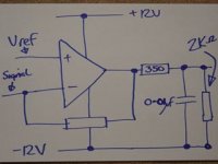
I simply biased my LM 6182 cd723 o/p device into class A using two 2K resistors to the neg rail. I put them after the RC filter to avoid connecting the RF hash to the supply.
Judging from what I heard at the show I've just added a grand or to to the value of my player. It now sounds huge, relaxed and much cleaner in the mid and treble. I think I might try a new clock next that will replace the original one and feed the DAC.
I don't know if biasing op amps into class A would be quite as dramatic 1) in other cct's... or 2) if the amp following was not also class A, but I would stronly recommend that anyone using an op amp in any circiut to give this simple mod a try.
If you have this chip in a cd723 you're in for a real treat
mike
I saw that idea here from mikelm and thought that, yes, I can see the benefit of trying such a thing. In the past, I would not have thought much of such an idea, but my research into class D circuits has expanded my insight.
The resistors connect from the output of the chip to the negative supply rail of the chip to force it to keep supplying current from the positive rail so that the output transistors of the chip will not crossover completely. It is not very inefficient for such a low power circuit, or, rather, the losses are insignificant for the CD player.
It makes sense that in low-level circuits that any crossover distortion is amplified when the power amp drives the speaker, and what was a small amount in proportion to the total is still in the same proportion, but crossover distortion is so very egregious that even small amounts may have a negative subjective effect.
Frank Berry said:How did you bias the opamp into Class A operation?
Looking at the schematic for the LM6182, I can only see how you can create a d.c. offset by adding resistors to the negative rail.
Am I missing something?
I think it is more of an urban legend than anything else. the added resistor is more like another load to the output stage, except that it draws more from the positive side of the push-pull transistors. The switching is still there, assuming that you are not overloading the output stage.
Now, if you were to inject a small DC voltage to the signal such that you use only the one side of the push-pull, you are indeed eliminating the switching.
See your input is 20mvpp, and you add a +10mv DC signal to it. Now the combine signal swings from 0mv to 20mv peak. after the 10x opamp, it goes from 0mv to 200mv peak, all on one side of the opamp.
If you are really concerned about cross-over distortion, you can add a larger DC offset to the orignal signal, see 20mv, and your output will swing from 10x (20mv - 20mv/2) to 10x (20mv + 20mv / 2). and you are definitely in class A.
But I am not sure if that does anything to the sound.
subwo1 said:The resistors connect from the output of the chip to the negative supply rail of the chip to force it to keep supplying current from the positive rail so that the output transistors of the chip will not crossover completely.
it will cross-over completely. except in this case, the upper transistor in the PP stage "pushes" out more current, and the lower transistor in the PP stage "pulls" in less current, when they are conducting during their respective cycles. Both are conducting exactly 180 degrees, as they did without the added resistor.
otherwise, you would have created DC offset at the output.
To me, the only way you get a class B amp to work in Class A is if you inject intentionally a DC offset (at the input) so that only one of the two transistors in the PP stage conducts during 360 degrees. You can then use a cap to filter out the DC offset (at output).
here is the cct
because the load is much higher resistance that the 2Kohm resistor to the neg rail whatever happens dc will always flow through only one of the chip o/p tranistors to the neg. The signal will be modulated onto this dc - class A
probably it's more elegant to use a current source - might sound better
mike
Attachments
millwood said:To me, the only way you get a class B amp to work in Class A is if you inject intentionally a DC offset (at the input) so that only one of the two transistors in the PP stage conducts during 360 degrees.
I simulated a push-pull stage (2n5551+2n5401, no feedback and no bias) driven by a 2vpp 1Khz signal. THD at 46%. Adding a 2v DC offset to the input signal gets THD at 0.5% from the same circuitry.
mikelm said:because the load is much higher resistance that the 2Kohm resistor to the neg rail whatever happens dc will always flow through only one of the chip o/p tranistors to the neg. The signal will be modulated onto this dc - class A
all it does, Mike, is that the upper transistor will work harder and the lower transistor will work less harder. Both will still switch on and off at exactly the same points.
mikelm said:probably it's more elegant to use a current source - might sound better
mike
a current source wouldn't do a whole lot of anything for you.
.
I would agree that its effect would not be class A if the output is having to drive a load through ground or a point between the power supply rails beyond a certain point. But if the amplitude of the output is able to be kept low enough, the class A operation could hold up.
all it does, Mike, is that the upper transistor will work harder and the lower transistor will work less harder. Both will still switch on and off at exactly the same points.
I would agree that its effect would not be class A if the output is having to drive a load through ground or a point between the power supply rails beyond a certain point. But if the amplitude of the output is able to be kept low enough, the class A operation could hold up.
from the point of view of an ac signal, ground, positive rail and negative rail are exactly the same. so tying a resistor to the negative rail does not achieve a whole lot of anything.
the same is true with a current source: to an ac signal, it is simply an infinetely large resistor / load.
what they (the resistor or the current source) do is to help the lower output transistor but add to the work of the upper output transistor.
the same is true with a current source: to an ac signal, it is simply an infinetely large resistor / load.
what they (the resistor or the current source) do is to help the lower output transistor but add to the work of the upper output transistor.
mlloyd1 said:I'm a little surprise you would sense such a big change - doesn't this device idle at about 10mA per op amp before this change?
Maybe I'm thinking about another part?
Ah well, if you like it, so be it
mlloyd1
Mm... got me thinking.
current is about 7mA according to the data sheet
I think it may be the RF noise and the low impedence filter that is drawing highish currents. There is no filter before the chip
I'll think on it some more and in the mean time enjoy the results...
")
millwood said:
a current source wouldn't do a whole lot of anything for you.
Hm, interesting then that Walt Jung recommends biasing op amps
into class a using a CCS, but what does he know?
Thanks Christer - I was hoping someone would say something decisive.
Millwood - I don't fully understand this idea, perhaps we should both do some research, simulation or thinking or some of each.
I do know, like 5th emement says, that I have just tried it and the audible effect was not small, so for sure something is going on.
Mike
Millwood - I don't fully understand this idea, perhaps we should both do some research, simulation or thinking or some of each.
I do know, like 5th emement says, that I have just tried it and the audible effect was not small, so for sure something is going on.
Mike
millwood said:from the point of view of an ac signal, ground, positive rail and negative rail are exactly the same. so tying a resistor to the negative rail does not achieve a whole lot of anything.
the same is true with a current source: to an ac signal, it is simply an infinetely large resistor / load.
what they (the resistor or the current source) do is to help the lower output transistor but add to the work of the upper output transistor.
What the resistor do, is to force one of the output transistors to supply more DC current...so it become more heavily biased...and work in a more rich classe A/B.
But there are some drawbacks in it...mere suplly noise at the output of the op amp...and a small increase in distortion as the load is smaller.
Nothing is perfect!
In my cct the supply is very quiet, C L C L C L C regulation !!!
I am more worried about the RF noise at the o/p polluting the rails.
I was thinking about using a separate supply for each resistor...
A CCS would help with the noise is it were fast enough.
This chip can drive video signal into 75ohms so driving into 2kohms should be OK.
mike
I am more worried about the RF noise at the o/p polluting the rails.
I was thinking about using a separate supply for each resistor...
A CCS would help with the noise is it were fast enough.
This chip can drive video signal into 75ohms so driving into 2kohms should be OK.
mike
- Status
- This old topic is closed. If you want to reopen this topic, contact a moderator using the "Report Post" button.
- Home
- Amplifiers
- Solid State
- The sound of two transistors switching