Voltage drop
Hi SSS....
Your idea is very good and may be rarely to be used by others... but you may concern about max. current and voltage that can be delivered and how much voltage drop....how about thermal dissipation on power transistor and diode?? It still need research and trial & error ...
Best regards,
Lukio
A voltge doubler power supply, how novel.
What do you need an oscillator for when you can use the audio itself?
These are called bootstrap caps.
A complete design with a bridge amp, bootstrap cap drive circuit, and class H output stage:
http://www.semiconductors.philips.com/pip/TDA1560.html
What do you need an oscillator for when you can use the audio itself?
These are called bootstrap caps.
A complete design with a bridge amp, bootstrap cap drive circuit, and class H output stage:
http://www.semiconductors.philips.com/pip/TDA1560.html
If you really have come up with a high efficieny inductorless voltage converter I'm sure you can get the Nobel prize for it.... I suggest that you fool around in LTSpice and explore your ideas.sss said:hey guys
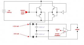
i got an idea to multiply the voltage of the car battery without using inductors of any kind , tell me what u think .
Who's afraid of coils and transformers? Not me.
It will certainly work but you may have noise problems. The junction of the two big capacitors that becomes the "earth" or at least the negative connection for the amplifier is going up and down by 12 volts at the same frequency as the square wave. So is the positive voltage to the amp.
This "common mode" voltage noise would be no big deal if you were floating in outer space right away from everything else, but if your equipment has any capacitance to ground (and it will) then you will get some high frequencies induced into the signal path. Also. if you plug anything into it that is connected to normal earth the smoke may escape from inside somewhere.
My suggestion is to put a second battery in series with the first one and run your stuff off this series combination. To keep the upper battery charged, *in principle* all you need is an inductor from the junction of the two batteries, a mosfet, a schottky diode and a controller chip.
Pull the free end of the inductor down to earth with the mosfet drain connection. Have the anode of the schottky diode connected from this free end of the inductor and the mosfet drain, the cathode end pointing toward the top of the upper battery.
When the mosfet lets the inductor go every cycle (~100kHz) it lets the inductor empty into the upper battery. The interesting this is that this dc/dc converter cct only needs to be rated at *half* the output power (but same amps) as what is drawn from the + of the top battery.
A suitable controller chip would be a xx3845. xx=manufacturer's prefix - made by several companies. 8 pin. Cheap. Not scary.")
It will certainly work but you may have noise problems. The junction of the two big capacitors that becomes the "earth" or at least the negative connection for the amplifier is going up and down by 12 volts at the same frequency as the square wave. So is the positive voltage to the amp.
This "common mode" voltage noise would be no big deal if you were floating in outer space right away from everything else, but if your equipment has any capacitance to ground (and it will) then you will get some high frequencies induced into the signal path. Also. if you plug anything into it that is connected to normal earth the smoke may escape from inside somewhere.
My suggestion is to put a second battery in series with the first one and run your stuff off this series combination. To keep the upper battery charged, *in principle* all you need is an inductor from the junction of the two batteries, a mosfet, a schottky diode and a controller chip.
Pull the free end of the inductor down to earth with the mosfet drain connection. Have the anode of the schottky diode connected from this free end of the inductor and the mosfet drain, the cathode end pointing toward the top of the upper battery.
When the mosfet lets the inductor go every cycle (~100kHz) it lets the inductor empty into the upper battery. The interesting this is that this dc/dc converter cct only needs to be rated at *half* the output power (but same amps) as what is drawn from the + of the top battery.
A suitable controller chip would be a xx3845. xx=manufacturer's prefix - made by several companies. 8 pin. Cheap. Not scary.
Re: Who's afraid of coils and transformers? Not me.
hello everyone
yeah i knew that , thats why i'm taking the input from a discman
so its not connected to the main ground
anyways this idea can be used in chip amps , that way u can get higher power with no smps
ps
the power dissipation in the H bridge is low because they only switch on and off
hello everyone
Circlotron said:It will certainly work but you may have noise problems. The junction of the two big capacitors that becomes the "earth" or at least the negative connection for the amplifier is going up and down by 12 volts at the same frequency as the square wave. So is the positive voltage to the amp.
This "common mode" voltage noise would be no big deal if you were floating in outer space right away from everything else, but if your equipment has any capacitance to ground (and it will) then you will get some high frequencies induced into the signal path. Also. if you plug anything into it that is connected to normal earth the smoke may escape from inside somewhere.
yeah i knew that , thats why i'm taking the input from a discman
so its not connected to the main ground
anyways this idea can be used in chip amps , that way u can get higher power with no smps
ps
the power dissipation in the H bridge is low because they only switch on and off
Hi !
I did not calculate the losses in your switching transistors.
But you switch them dircetly to capacitive load.
This will result in remarkable loss peak during each
switching moment. I would expect that you will not get a
very convincing efficiency. In case of small sized switching transistors
they may fail ....Just a feeling.... Calculate it, or try it...
Good luck
Markus
ChocoHolic said:Hi !
I did not calculate the losses in your switching transistors.
But you switch them dircetly to capacitive load.
those caps are not exactly capacitive loads , those are filter caps
i know that the start up current will be high , but this can be fixed easily
- Status
- This old topic is closed. If you want to reopen this topic, contact a moderator using the "Report Post" button.
- Home
- Amplifiers
- Solid State
- car amp power supply idea