Hi everybody…..
I’m a new comer for this forum, this is very good forum, I like it v’ much, really….!
After my fisrt CFB amp has some problems that I never know,
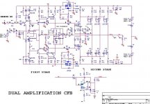
I’ve re- design of my CFB please give me advise for this circuit…Is there any potensial problem that I might meet?? I ‘m not build this design yet, waiting for comments from you all…. As per simulation, the performance is good.. Actually, I still don’t know…
Best regards,,
Lukio
I’m a new comer for this forum, this is very good forum, I like it v’ much, really….!
After my fisrt CFB amp has some problems that I never know,
I’ve re- design of my CFB please give me advise for this circuit…Is there any potensial problem that I might meet?? I ‘m not build this design yet, waiting for comments from you all…. As per simulation, the performance is good.. Actually, I still don’t know…
Best regards,,
Lukio
Attachments
Hi lukio. I have not come to any conclusion as to what is causing the problem in the other circuit you were having DC offset on, but maybe have a suggestion to test the stability of this circuit. Drive it with various capacitors on the output as a load and see what happens. Then add some compensation to see if you can stabilize it under all conditions. At the very least you may find the points where if needed, compensation is most effective.")
lukio said:
Do you think, is there any possibility for the amp to get oscillation?? Do I need to place the miller cap. at driver stage or freq. compensation on feedback network??
Hi.
Current Feedback amps must not have a capacitor in paralel with the feedback resistor,because is the value of the upper arm resistor of the feedback voltage divider,that define the bandwith.
If you want increase stability, increase a little the upper feedback resistor and make the some proporcional increase in the lower arm...( for the some overall closed loop gain).
Regards
Good advise
Hi...
Very thx for u all .....
I think sugestion from Jorge and Subwo1 are very good, I will try to connect capacitive load and also try to change the value of my feedback resistor as you said..... I'm not try that methode yet..
Music and Amp is an art......it can express you ....
Hi...
Very thx for u all .....
I think sugestion from Jorge and Subwo1 are very good, I will try to connect capacitive load and also try to change the value of my feedback resistor as you said..... I'm not try that methode yet..
Music and Amp is an art......it can express you ....
"Current Feedback amps must not have a capacitor in paralel with the feedback resistor,"
Odd thing to say.... Since I'm listening at this very moment to a a CFB amp with just such a cap. However, mine has a damping resistor in series with; the valur is equal to that of the resistor in the lowert arm. The function of this arrangement is to create a frequency dependant voltage divider with the result that the overall gain falls back to unity at high frequencies sooner than it otherwise would. Since phase lag increases with frequency the idea is to pull the gain down before the phase lag reaches 180 deg.
All that is easy enough to say. The problem in implementation is that it seems quite hard to figure out what the value should be without experomentation. The calculations required are beyond me and Spice analysis assumes an ideal case wich isn't what you get when you build a real amp. Further, a very small change in the value can have pretty drastic results.
are you talking about the amp you descrive in the post 6 ofsam9 said:"Current Feedback amps must not have a capacitor in paralel with the feedback resistor,"
Odd thing to say.... Since I'm listening at this very moment to a a CFB amp with just such a cap.
http://www.diyaudio.com/forums/showthread.php?s=&threadid=27067&perpage=15&pagenumber=1
?
No. I'm still working with that one. The one I have in mind was completed last spring and is a 50Wer with a single output pair. It had a couple of problems as well, but the cure was simply to change the PCB to keep section as far away from the IS and VAS as possible. It was basically a Slone design but with a PCB laid out to fit the enclosure I was using.
This new one is derived from that with two main changes a nominal 100Wer with another output pair and a diode bias for the CCs. Also the layout of the PCB had some quirks due to how I wanted to mount it plus some options so I could try a couple of circuit variations. When I get it working how I want, I'll follow up that thread to tell what I did. Right now, I'm beginning to fear that I've been soldereing-desodering-resoldering some components so often that board is becomming a bit manky. I may need to etch a fresh one.
This new one is derived from that with two main changes a nominal 100Wer with another output pair and a diode bias for the CCs. Also the layout of the PCB had some quirks due to how I wanted to mount it plus some options so I could try a couple of circuit variations. When I get it working how I want, I'll follow up that thread to tell what I did. Right now, I'm beginning to fear that I've been soldereing-desodering-resoldering some components so often that board is becomming a bit manky. I may need to etch a fresh one.
According to my experiments with CFB amplifiers, the PSU of the input stage has a big impact on the overall results, as the PSRR of this kind of circuit is poor.
I see you used some LM317 regulators, but an additional R-C low pass might be a very cheap way to further improve the design.
I see you used some LM317 regulators, but an additional R-C low pass might be a very cheap way to further improve the design.
AMT-freak said:According to my experiments with CFB amplifiers, the PSU of the input stage has a big impact on the overall results, as the PSRR of this kind of circuit is poor.
Yes it is!! And also the DC precision...but they excel in slew rate and in a bandwith that is less independent of the open loop gain...
- Status
- This old topic is closed. If you want to reopen this topic, contact a moderator using the "Report Post" button.
- Home
- Amplifiers
- Solid State
- Please comment for my new CFB amp