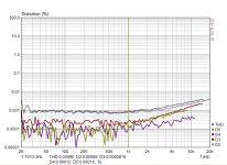
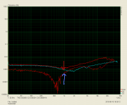
I like the measurements - distortion is low enough in the wide range of amplitudes.
The profile is also nice - mainly H2, H3, H5, all the rest is much lower.
THD increase is not significant at 10-20KHz, meaning the open loop bandwidth is rather wide.
Do you plan to audition this one?
The profile is also nice - mainly H2, H3, H5, all the rest is much lower.
THD increase is not significant at 10-20KHz, meaning the open loop bandwidth is rather wide.
Do you plan to audition this one?
Yes, i will go for second chanel this time with lower compensetion after C15 remove.I like the measurements - distortion is low enough in the wide range of amplitudes.
The profile is also nice - mainly H2, H3, H5, all the rest is much lower.
THD increase is not significant at 10-20KHz, meaning the open loop bandwidth is rather wide.
Do you plan to audition this one?
Then i will listen in stereo.
I had listen mono for a little in a cheep full range speaker nice sounding very analytic good bass and nice high.
During test 4R7 floating resistor smoked and a separate wire (red crocodile in the picture) used that connected in a clear gnd.
This connection is away, no hum at all and fft in 50Hz region is as the day and night!
thimios
Val
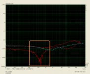
If may I add a 2 cents from myself. I have learned a lesson that measuring THD is a good approach to check if the amplifier is well made (and still learning). Some bad things (a small oscillations of very low amplitude) can occur at various different amplitudes, temperatures and loads.
thimios - You are making a very good work of testing the circuit at different condidtions, please check for a sharp changes in THD profile, it may indicate some potential problems. They does not have to be present now but in matter of time they may occur.
Bellow I have attached some my bad examples + one good with nice, smooth and predictable THD response.
As far I remember some of the sharp curves on THD responses (like marked with orange square on sauberkeit plot) I have sorted with adding a few base stopper resistors.
Good work!!
Regards
Val
If may I add a 2 cents from myself. I have learned a lesson that measuring THD is a good approach to check if the amplifier is well made (and still learning). Some bad things (a small oscillations of very low amplitude) can occur at various different amplitudes, temperatures and loads.
thimios - You are making a very good work of testing the circuit at different condidtions, please check for a sharp changes in THD profile, it may indicate some potential problems. They does not have to be present now but in matter of time they may occur.
Bellow I have attached some my bad examples + one good with nice, smooth and predictable THD response.
As far I remember some of the sharp curves on THD responses (like marked with orange square on sauberkeit plot) I have sorted with adding a few base stopper resistors.
Good work!!
Regards
Attachments
Tribute 3000
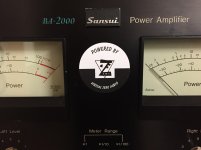
I just wanted to mention that the "21st Century Protection System" was not the problem, It was just doing it's job.") I had a shorted Zener and transistor in the Sansui regulated supply for the driver boards.
I had a shorted Zener and transistor in the Sansui regulated supply for the driver boards.
I got that sorted and everything is as it should be. I still have to wire the meters and a couple more mechanical things to finish it up but I am really happy with it.
I have had a chance to listen and its good. In the last five years I’ve had a single ended tube amp using a type 45 output tube. A push pull tube amp using KT88’s, another tube amp using paralleled TV sweep tubes, I had Lazy Cat's VSSA 150w amp, an Accuphase E-303, and a restored Sansui AU-9500 and a restored BA-2000. I enjoyed listening with all these amps but I kept returning to the 9500. Choosing it over all the rest.
Now I have the modified BA-2000. This amp has all the detail of a modern amplifier but it still has that Sansui 9500 ....charm? The modified BA-2000 has the detail, separation of instruments and smooth vocals of a modern amplifier that I like but has other qualities that remind me of the 9500. Sustain on guitar strings and cymbals are absolutely real. Vocals are again, authentic and live.
I love the looks of the old Sansui amps and it makes me happy to have the best of the new and old. I wish I could fit the Tribute boards in the AU-9500.:-0
Thank you Valery and Jeff.
I just wanted to mention that the "21st Century Protection System" was not the problem, It was just doing it's job.
I had a shorted Zener and transistor in the Sansui regulated supply for the driver boards.I got that sorted and everything is as it should be. I still have to wire the meters and a couple more mechanical things to finish it up but I am really happy with it.
I have had a chance to listen and its good. In the last five years I’ve had a single ended tube amp using a type 45 output tube. A push pull tube amp using KT88’s, another tube amp using paralleled TV sweep tubes, I had Lazy Cat's VSSA 150w amp, an Accuphase E-303, and a restored Sansui AU-9500 and a restored BA-2000. I enjoyed listening with all these amps but I kept returning to the 9500. Choosing it over all the rest.
Now I have the modified BA-2000. This amp has all the detail of a modern amplifier but it still has that Sansui 9500 ....charm? The modified BA-2000 has the detail, separation of instruments and smooth vocals of a modern amplifier that I like but has other qualities that remind me of the 9500. Sustain on guitar strings and cymbals are absolutely real. Vocals are again, authentic and live.
I love the looks of the old Sansui amps and it makes me happy to have the best of the new and old. I wish I could fit the Tribute boards in the AU-9500.:-0
Thank you Valery and Jeff.
Wow! that would be exciting. I don’t know if there is room for 6 outputs per side on the Sansui AU-9500 heatsink though. I had been looking at the lichstark and simplestark boards wondering if I could get them to fit but I suppose would lose the Sansui flavor..
I am going to use some of your boards 1 way or another though. I’m hooked on bringing these old Sansui into the 21st century.
It reminds me of the Hennessy or Saleen Ford Mustang. That look pretty normal on the outside but supercharged under the hood.
Thanks again
.I am going to use some of your boards 1 way or another though. I’m hooked on bringing these old Sansui into the 21st century.
It reminds me of the Hennessy or Saleen Ford Mustang. That look pretty normal on the outside but supercharged under the hood.
Thanks again
But valery dont you think the distortion is still high as at higher frequencies. I see with Tube sumo you have got very low distortion even in HF.I like the measurements - distortion is low enough in the wide range of amplitudes.
The profile is also nice - mainly H2, H3, H5, all the rest is much lower.
THD increase is not significant at 10-20KHz, meaning the open loop bandwidth is rather wide.
Do you plan to audition this one?
Hi Valery and Thimios,
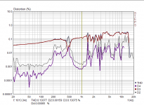
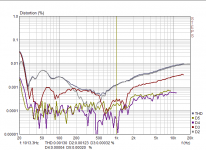
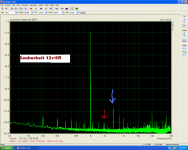
another point about the last measurement of sauberkeit.
If I look at the 1kHz THD measurement D3 > D2.
But in the measurement of steps D2<D3.
Are the steps measurement was made with different power?
another point about the last measurement of sauberkeit.
If I look at the 1kHz THD measurement D3 > D2.
But in the measurement of steps D2<D3.
Are the steps measurement was made with different power?
Attachments
Very nice!!
Will it have similar specs (aside power) than the NS OPS? Will it have capability to exchange IPS?
I’m really interested to assemble one for my 15" subwoofer.
Thanks
Do
Hi Do,
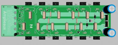
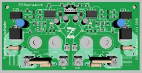
Yes, it's based on the same circuitry as an earlier NS Double Power design, but the layout is adapted to the less exotic form-factor - the previous version looked more like a square. It supports the similar set of IPS modules - you can see a ground plane on the left side of the main board - the IPS module will be placed right above it. The board with the binding posts contains the Zobel + Thiele networks, DC offset protection and SS relays.
High-power PSU and high-gauge rails / ground wiring are expected
Cheers,
Valery
6 pair Monster!We have a new monster in the works! A NS amplifier designed for a stereo chassis designed to produce up to 600W per channel using readily available On Semi drivers and output devices.
What the purpose of all these TO220 transistors on the main heatsink?
I guess that a giant heatshink and force cooling will be necessary to keep this in the safe side.
What is the final transistors, bjt or fet?
Sure this isn't a toy for playing with.
What is the max power supply voltage?
I like the N.S IPS compatibility!
I think that i can test the rest of the IPS soon.
Last edited:
6 pair Monster!
What the purpose of all these TO220 transistors on the main heatsink?
I guess that a giant heatshink and force cooling will be necessary to keep this in the safe side.
What is the final transistors, bjt or fet?
Sure this isn't a toy for playing with.
What is the max power supply voltage?
I like the N.S IPS compatibility!
I think that i can test the rest of the IPS soon.
The TO220s are the drivers for the output transistors. I've noticed a lot of variation in bias current with the drivers mounted on their own heat sinks with the new output devices. Everything is more stable with them mounted on a larger hunk of aluminum.
The output devices are MJL4302/4281. They're rated for 350V so if anyone is psychotic enough to try it 100+ rails should theoretically be possible. I have a 64VAC transformer kicking around so I could do some testing at +/- 90V rails but I don't need that much power for anything so I wouldn't run it like that.
I'm planning to test this in a 5U 16" deep convection cooled chassis. It'll be a pretty heavy to move around but it should cool fine with +/- 70V rails.
The TO220s are the drivers for the output transistors. I've noticed a lot of variation in bias current with the drivers mounted on their own heat sinks with the new output devices. Everything is more stable with them mounted on a larger hunk of aluminum.
Can you elaborate a little more on how that hunk of aluminum should be for better stability?
- Home
- Amplifiers
- Solid State
- Revisiting some "old" ideas from 1970's - IPS, OPS