I have to be honest even after building various amps getting the ground right eludes me and is more a matter of luck. Is there a standard, guaranteed, repeatable formula for getting no hum?
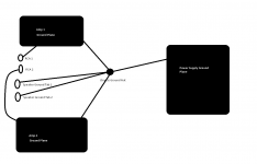
Lets use this pic I have attached below as the base reference level. What would need to be changed below for "perfect" repeatable zero hum? All of the black lines obviously are grounding wire and the ground planes are on separate PCBs. Also, does the gauge of the wires play a role, especially for the RCA connectors?
Lets use this pic I have attached below as the base reference level. What would need to be changed below for "perfect" repeatable zero hum? All of the black lines obviously are grounding wire and the ground planes are on separate PCBs. Also, does the gauge of the wires play a role, especially for the RCA connectors?
Attachments
Is there a standard, guaranteed, repeatable formula for getting no hum?
The devil is in the details, but here's a good article.
http://www.diyaudio.com/forums/diya...udio-component-grounding-interconnection.html
Also, please discuss the important of non-ground wires such as transformer mains or secondaries.
Those should be twisted pairs, or triples if with a center tap.
Last edited:
Here's your Absolute Final Answer, though you may not like it:
Sound System Interconnection
But read the whole thing (and read through Tom's Modulus-86 thread regarding why he uses a balanced input chip even in "unbalanced" mode), understand where ground currents come from (several sources), where they enter equipment (probably at the ground pins of those RCA connectors) and where they connect internally in the amp (ideally, to the 'ground' side of the series resistor/capacitor pair that connects to the negative or "feedback" input of the LTP input transistors - NOT the "star" or chassis ground). That doesn't do RF shielding of the input, but a small capacitor between the RCA connector ground and that point on the chassis will fix that.
IMHO, if you rely on wire gauge (even with a few other blind shotgun blasts), you'll only reduce hum somewhat, not eliminate it.
If you treat each piece of equipment as a black box as you show in your diagram (and you don't even show the other "black boxes" that any system would have), your only guarantee is to use those expensive audio isolation transformers the article mentions. Those audio transformers are pretty good (they're between studio microphones and preamps, and in line-level signals in recording consoles), but they do have an audible effect on sound.
Sound System Interconnection
Summary
If you are unable to do things correctly (i.e. use fully balanced wiring with shields tied to the chassis at the point of entry, or transformer isolate all unbalanced signals from balanced signals) then there is no guarantee that a hum free interconnect can be achieved, nor is there a definite scheme that will assure noise-free operation in all configurations.
But read the whole thing (and read through Tom's Modulus-86 thread regarding why he uses a balanced input chip even in "unbalanced" mode), understand where ground currents come from (several sources), where they enter equipment (probably at the ground pins of those RCA connectors) and where they connect internally in the amp (ideally, to the 'ground' side of the series resistor/capacitor pair that connects to the negative or "feedback" input of the LTP input transistors - NOT the "star" or chassis ground). That doesn't do RF shielding of the input, but a small capacitor between the RCA connector ground and that point on the chassis will fix that.
IMHO, if you rely on wire gauge (even with a few other blind shotgun blasts), you'll only reduce hum somewhat, not eliminate it.
If you treat each piece of equipment as a black box as you show in your diagram (and you don't even show the other "black boxes" that any system would have), your only guarantee is to use those expensive audio isolation transformers the article mentions. Those audio transformers are pretty good (they're between studio microphones and preamps, and in line-level signals in recording consoles), but they do have an audible effect on sound.
No such thing as zero hum, but sufficiently low hum can be achieved.
There is no rule/formula/recipe, apart from: don't follow rules!
Instead, learn about circuits: current always flows in loops, voltage always exists between two points (not one point), every conductor is both a resistor and inductor, every AC circuit loop will couple magnetically to every other circuit loop, every AC circuit node will couple capacitively to every other circuit node.
One thing to avoid is using the chassis as part of your active signal ground, as you have it in post 1. Never fall into the trap of believing (as some seem to do) that hum and other interference can be 'sunk'/'drained' into the chassis or other ground. Instead, pick your ground refererence point (or bus) and ground all signals back to that. Then, put a separate connection from the clean quiet PSU output to the chassis. Finally, connect the chassis to the incoming mains ground (if you have one).
There is a lot on grounding on this forum, and elsewhere on the web. The snag is that some of it is nonsense!
- Status
- This old topic is closed. If you want to reopen this topic, contact a moderator using the "Report Post" button.