I just looked to tone control circuit, problem may be comes from there.Did you tried connect signal to 20k directly,not usung 4558 outputs.
Anyway here you are my cicruit for you easy and powerfull and not expensive working 100% no headache and more better tone control.
It is your disition ofcourse.Good luck.
Anyway here you are my cicruit for you easy and powerfull and not expensive working 100% no headache and more better tone control.
It is your disition ofcourse.Good luck.
Attachments
Look at the recommended layout. It confirms that the grounding layout is unusual and obviously important.
The important thing to note here is that the star ground is located at the ground pin of the chip. Not at the negative lead of the reservoir cap as is customary. Makes it much more difficult to implement two on a common board - especially with a single sided board. Last time I fooled around with TDA2002's I ended up clamshelling a heat sink in between two of them so I could get the two ground pins as close together as possible.
Hi wg_ski,
I've serviced a few chip amps that used the filter cap negative as the signal ground end point and they were fine. They just made the ground pin a short, fat trace to that point.
In any event, using chips like these will make you a better designer because you must be that much better in laying out your circuits. In the case of this chip, it seemed important to keep low current common connections close to this ground pin, then to the filter capacitor ground where the speaker return and RF connected. I have never designed a PCB for one of these, but I had plenty to service.
Another "chip" like amp were those old ILP modules (potted circuit board on a heat sink). These would blow up if you didn't get the grounding exactly right. Much like these real grumpy old ICs with exacting requirements.
Hi Batson,
It's too easy to recommend someone use your favorite chip (in this case), but when the other person has the parts and wants to use them, try and help along those lines, or hold your peace. So he's using a chip that is harder to use than others. I applaud mitsof for sticking to his decision and making something that works - assuming he sticks with this chip.") He built the amp before asking for help, meaning he was brave enough to try a new thing. Now he is asking for help at a point where he will learn much from this experience. Hand this fellow a chip amp next year and he will probably get it working the first time, every time.
He built the amp before asking for help, meaning he was brave enough to try a new thing. Now he is asking for help at a point where he will learn much from this experience. Hand this fellow a chip amp next year and he will probably get it working the first time, every time.
-Chris
I've serviced a few chip amps that used the filter cap negative as the signal ground end point and they were fine. They just made the ground pin a short, fat trace to that point.
In any event, using chips like these will make you a better designer because you must be that much better in laying out your circuits. In the case of this chip, it seemed important to keep low current common connections close to this ground pin, then to the filter capacitor ground where the speaker return and RF connected. I have never designed a PCB for one of these, but I had plenty to service.
Another "chip" like amp were those old ILP modules (potted circuit board on a heat sink). These would blow up if you didn't get the grounding exactly right. Much like these real grumpy old ICs with exacting requirements.
Hi Batson,
It's too easy to recommend someone use your favorite chip (in this case), but when the other person has the parts and wants to use them, try and help along those lines, or hold your peace. So he's using a chip that is harder to use than others. I applaud mitsof for sticking to his decision and making something that works - assuming he sticks with this chip.
He built the amp before asking for help, meaning he was brave enough to try a new thing. Now he is asking for help at a point where he will learn much from this experience. Hand this fellow a chip amp next year and he will probably get it working the first time, every time.-Chris
AV-502 Amp PCB Design Help Plz.
Hi, can anyone have a PCB design of this schematic pls? i had pretty hard time to do it because i am not good in PCB design softwares, i just want to build this one:
Tnx in advance
Hi, can anyone have a PCB design of this schematic pls? i had pretty hard time to do it because i am not good in PCB design softwares, i just want to build this one:
An externally hosted image should be here but it was not working when we last tested it.
Tnx in advance
Hi Jefferson,
Okay, now I am going to recommend that you look at some different amplifier designs that were done here at DIYAudio. Specifically, have a look at the Symasym (do a search) as it turned out great and there are both PCB layouts and reports on the finished amplifier. This one would use the + / - 35 volt supplies you have shown. There are several known quantities for amplifiers running at higher voltages. One member has designed a higher power amplifier for the site called the "Honey Badger". His screen name is ostripper, and he has other very good designs available too. I am positive you would find something there to your liking.
I have built the Symasym (for a utility amplifier) and the performance greatly exceeded my expectations, so I am biased a little. But that amplifier was designed for the 35 volt rails you are looking at. It is rated at 50 watts output power, and it is very clean. I ended up building more of these that were higher power for another project. I was not disappointed.
The main reason I suggested something else was the need you have for a PCB layout. If you followed the original Symasym thread, there is a point where the layout was changed and the performance was improved. The layout can make or break an amplifier - as you should know now! For this reason I think you should build a design that has the bugs worked out of it.
-Chris
Hi guys,
I have built the stereo audio circuit under the document at page 5:
https://construyasuvideorockola.com/downloads/tda2003.pdf.
I want to use the USB audio Bluetooth (audio output is jack 3.5mm) to provide the audio signal for this circuit.
I have provided 12VDC (from ATX power supply) for the audio amplifier circuit and the USB audio Bluetooth (using IC 7805 to convert from 12v to 5v for it).
My problem is that when I connected the audio output from USB to the audio amplifier circuit, I could hear the whistling sound. I tried changing the USB power supply with my phone charger and no whistling sound.
How to no longer whistling sound?
sorry for my English is not good.
It seems that you have a whole mess of devices there. I think you said that your your problem was a high pitched noise (a whistling sound?) when using the Bluetooth adaptor + amplifier, all powered from the PC power supply. If so, the problem could be difficult to eliminate with a such a simple amplifier as this, which has no input filtering. PC power supplies are grounded to the mains and are very noisy, usually causing bad hum on USB audio devices, which is why optical and Bluetooth links are often necessary when using the PC as an audio source.
However, when you power the Bluetooth adaptor separately, the noise disappears, so why not use them with separate and adequate power supplies, (as in supplying enough current) in this way? Have you tried your Bluetooth adaptor with a another amplifier?
However, when you power the Bluetooth adaptor separately, the noise disappears, so why not use them with separate and adequate power supplies, (as in supplying enough current) in this way? Have you tried your Bluetooth adaptor with a another amplifier?
Hi Ian,
I have tried my Bluetooth adaptor with an another amplifier and there is no noise.
I use lithium-ion batteries to power the amplifier circuit and the Audio Bluetooth device because i want my speakers to be portable.
But, i was not lucky today. I powered 24v for my circuit and one capacitor (470uF 16v) and one TDA2003 explored
Things start again from the beginning
TDA2003 with 7824 + 7818
Dear Sir,
last night i have build TDA2003 with 7824 + 7818 and Fast Diode Bridge,
its sound very good and cleaned,
Thanks
I got a loud noise in amp tda2003 amp.
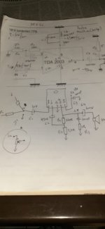
When I connect the amp to a 12volt battery the noise in my speaker ca be barely heard.But when I connect it to an unregulated power supply (15volt transformer,rectifier,4700uF capacitor) I get a loud noise.
I did some experimenting -added an LM78.. regulator.At 18volts I get the noise.At 15volts the same.But at 12 volts the noise is gone.Maybe its volume is reduced enough not to be detectable by ear.
I tried to move cables around within the enclosure-power cables away for audio cables but nothing happens. I even took the transformer entirely out of the metal box .The result is that the noise get even louder.
I suspect a ground loop,a cold solder connection or even a bad component.I have no idea how to pinpoint the problem.Maybe its the tdas themselves.
What else can I try?
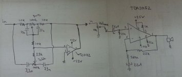
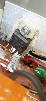
Here are the schematics and some pictures of the amp within the metal case.
As DIY as it gets! ????????????????: TDA2003 stereo amplifier with tone control 20 watts (10+10)
Dear Sir,
last night i have build TDA2003 with 7824 + 7818 and Fast Diode Bridge,
its sound very good and cleaned,
Thanks
Attachments
- Home
- Amplifiers
- Solid State
- Noise in my stereo tda2003 amp