...4 transistors.
After playing around a bit with some SET amplifiers, I thought that for the heck of it I'd like to make a MOSFET SE amplifier. Obviously inspired by Nelson Pass's ZEN type amps ("the sound of one fet clipping"), but I wanted to go with an original design for the usual basically irrational reasons. The target was for about 8W at 4 ohms for comparison to a 300B amp built by a friend, found to be plenty adequate for driving my speakers and having some nice subjective effects. I also wanted to get better than average MOSFET SE distortion and damping factors and practical efficiency (for class A, anyway).
I went through a lot of SPICE models and came up with various designs with and without feedback, using P-channel inputs and/or outputs, current source loads, inductor loads, common source outputs, source follower outputs, enhancement mode, depletion mode, different numbers of stages (1,2,3).
Eventually, the attached is what I came up with after both SPICE and bench tweaking. A good balance between performance and circuit simplicity, I think.
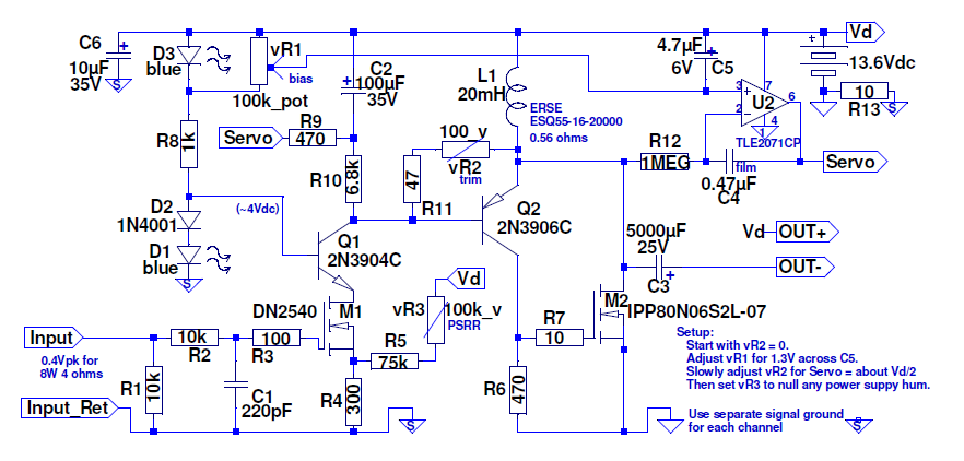
It uses a single supply and an inductor current source, somewhat along the lines of SET amplifiers with their output transformers that use the inductance to provide the energy for the positive signal swing (about double efficiency you'd get with an active current source). The circuit will run off as low as 11VDC and to quite a bit higher voltage than the 13.6V I use (higher voltage BJT parts, more heatsinking or fans, and/or higher speaker impedances and standby current settings likely needed for that, though!). For 8W at 4 ohms, the standby current needs to be about 2A from the 13.6V supply (I set it for 2.2A and get about 9W output).
The inductors I used were 20mH large 'dogbone' crossover inductors made by ERSE. These have huge 'gaps' and aren't likely to saturate the way they are used here. They should ideally have higher inductance, as being ony 20mH limits output power starting below about 30Hz. I cross my speakers to subs at 70Hz, so it isn't a problem. If you use other inductors watch the current ratings!. TRIAD C-49U looks interesting.
Before the circuit got to the bench, it had only three transistors (a DN2540 input MOSFET, and a BJF/NMOS SziklaiCFP type follower output). It looked really good in SPICE, but not so much on the bench. SPICE apparently doesn't model the nonlinear drain-source capacitance of the DN2540 very well! Distortion was decent with the DN2540 driven directly from a low impedance, but was horrible with a realisitc input driving impedance. So if the DN2540 was to remain, the choices were to either include an input buffer, change to a LTP arrangement or cascode. Cascoding was the simplest way that modeled well, so Q1, D1 and D2 were added. Not too much added complication. Some distortion spectra graphs are coming in the next post!
I thought this was all a very clever arrangement while I was getting it going, but have since seen about every aspect (maybe not all together, but separately at least) of it in some other projects posted here. And of course the class A output powered through an inductor is an old stand-by technique from 60's vintage Delco car radios (those even connected the speaker right across the inductor, so the speaker got DC as well!).

After playing around a bit with some SET amplifiers, I thought that for the heck of it I'd like to make a MOSFET SE amplifier. Obviously inspired by Nelson Pass's ZEN type amps ("the sound of one fet clipping"), but I wanted to go with an original design for the usual basically irrational reasons. The target was for about 8W at 4 ohms for comparison to a 300B amp built by a friend, found to be plenty adequate for driving my speakers and having some nice subjective effects. I also wanted to get better than average MOSFET SE distortion and damping factors and practical efficiency (for class A, anyway).
I went through a lot of SPICE models and came up with various designs with and without feedback, using P-channel inputs and/or outputs, current source loads, inductor loads, common source outputs, source follower outputs, enhancement mode, depletion mode, different numbers of stages (1,2,3).
Eventually, the attached is what I came up with after both SPICE and bench tweaking. A good balance between performance and circuit simplicity, I think.
It uses a single supply and an inductor current source, somewhat along the lines of SET amplifiers with their output transformers that use the inductance to provide the energy for the positive signal swing (about double efficiency you'd get with an active current source). The circuit will run off as low as 11VDC and to quite a bit higher voltage than the 13.6V I use (higher voltage BJT parts, more heatsinking or fans, and/or higher speaker impedances and standby current settings likely needed for that, though!). For 8W at 4 ohms, the standby current needs to be about 2A from the 13.6V supply (I set it for 2.2A and get about 9W output).
The inductors I used were 20mH large 'dogbone' crossover inductors made by ERSE. These have huge 'gaps' and aren't likely to saturate the way they are used here. They should ideally have higher inductance, as being ony 20mH limits output power starting below about 30Hz. I cross my speakers to subs at 70Hz, so it isn't a problem. If you use other inductors watch the current ratings!. TRIAD C-49U looks interesting.
Before the circuit got to the bench, it had only three transistors (a DN2540 input MOSFET, and a BJF/NMOS SziklaiCFP type follower output). It looked really good in SPICE, but not so much on the bench. SPICE apparently doesn't model the nonlinear drain-source capacitance of the DN2540 very well! Distortion was decent with the DN2540 driven directly from a low impedance, but was horrible with a realisitc input driving impedance. So if the DN2540 was to remain, the choices were to either include an input buffer, change to a LTP arrangement or cascode. Cascoding was the simplest way that modeled well, so Q1, D1 and D2 were added. Not too much added complication. Some distortion spectra graphs are coming in the next post!
I thought this was all a very clever arrangement while I was getting it going, but have since seen about every aspect (maybe not all together, but separately at least) of it in some other projects posted here. And of course the class A output powered through an inductor is an old stand-by technique from 60's vintage Delco car radios (those even connected the speaker right across the inductor, so the speaker got DC as well!).
Last edited:
I was hoping to get 8W from 12VDC (there being a lot of 12V reguated power supplies around, made for bench testing of car radios and autosound). For new builders, it is relatively difficult to hurt yourself too bad when working with just a 12V supply, so that would be good if anyone else wanted to make the design. Unfortunately I couldn't quite get to 8W using only 12V when the cascode was added, which isn't a huge deal. But the 12V regulated bench supplies had a problem I hadn't considered at first: they almost invariably have noisy fans! So instead, I got a cheap steel enclosure off the 'bay and made a simple "linear" supply using a TRIAD VPS24-5400 (wired for 12VAC), a 25A bridge rectifier and 60,000uF of filter capacitors. The heatsinks were also from the 'bay (Sunetec SS830). Heatsinking type is important on this one, as there's just one power device but about 35W to get rid of!
The design is 'sorta' a 2-stage design, with the M1/Q1 cascode acting as the input stage and providing all of the voltage gain. Q2/M2 act as a high-performance emiiter follower providing the output current and a nice low output impedance (50mOhms, if SPICE is to be believed). Note that the output comes (capacitor coupled) between the MOSFET drain and the POSITIVE supply (not ground)! U2 acts as a servo to force the standby current stable. FETS being the loosely-specified things that they are, a trimmer (vR2) is needed to set the servo's output in the middle of its range. vR1 sets the standby current, which will equal the voltage across C5 divided by the DC resistance of inductor L1. You can change R1 to something larger if you want higher input impedance than the 10k I used. You can also add film caps across C3 if you want.
The circuit topology provides about 25dB of power supply rejection, which isn't a lot when dealing with the ripple from a supply doing several amperes continuously! vR3 injects a tiny bit of the supply noise into the input stage to null out (cancel) any supply ripple that would otherwise get through. This works quite well, the background is dead silent after adjustment, even on horn speakers.
Here are some distortion spectra at 1.11kHz when driving a 4 ohm load to 1 Watt (about 0.06%, mostly 2nd harmonic) and to 8 Watts (0.25% essentially 2nd and 3rd). (the odd frequency chosen to avoid common USB soundcard leakage at 1kHz).
Last edited:
Here are some spectra at 11.11kHz, 4 ohms.
1Watt (0.15%, predominantly 2nd) and 8Watts (0.45%, mostly 2nd).


1Watt (0.15%, predominantly 2nd) and 8Watts (0.45%, mostly 2nd).
Last edited:
Some lessons learned:
1) DON'T USE A THIN STEEL ENCLOSURE FOR THESE AMPS! The magnetic field from the power transformers makes the panels hum. And fields from the big inductors modulates the panels, so you can hear tones during bench testing! Bracing and damping all the panels wasn't easy.
2) DON'T USE TOO SMALL AN ENCLOSURE! I had a lot of trouble for a while because the bridge rectifier was too near some of the ground leads and injected noise into the input, but only when the two input shields were connected in common (such as at the system preamp). Resistors R13 and the grounding arrangement eventually fixed this, but the rectifier should ideally not be right next to the connectors on the back panel!
3) DON'T USE *THIS* ENCLOSURE! I turned out to be really difficult to get it all wired together because of the way the cover connects and the need to get wires to and from the little board mounted on the heatsinks. A better sized aluminum enclosure would be a lot better choice (maybe next time). I do like the "Steam Punk" look of this one, though, with the big dog-bone inductors mounted on top.
4) DN2540 IS EASY TO BLOW UP WITH STATIC OR LEAKAGE VOLTAGES DURING CONSTRUCTION. I blew up about half a dozen of them at irregular times until discovering a significant voltage between my soldering iron tip and the (then) ungrounded ouptut of a bench supply I was using. I also blew one up by not discharging myself before grabbing the gate terminal with a tool. So usual anti-static cautions are advised. Buy some spares, the parts are cheap in TO-92 form (what I used). The tell-tale sign that it is popped is when DC voltage appears on the gate lead.
5) CHECK THE POLARITY OF THE LEDS BEFORE WIRING -- usually the "flat" part of the lens is the cathode. Except when it isn't, some are inexplicably swapped! Look carefully at data sheets or test with a resistor and bench supply before soldering into a circuit.
6) The thing gets HOT (including the rectifier bridge). Fuse everything well and best not leave it running unattended for long. (Being SE Class A, though, do play it as loud as you want -- the devices are happier the more the power goes out the speaker terminals instead of out the heatsink. 8W plays a lot louder, clean, than you might think).
Last edited:
Other characteristics -
No turn-on thump.
Slight turn-off thump (not as loud as the toggle switch even).
Stable into open, short, inductive, capacitive loads (tested to 2uF).
Nearly impossible to blow speaker (because of output capacitor).
Very well-behaved in general.
Input is DC connected (so if preamp has DC on its output, use a series cap!).
Bandwidth (if input filter cap removed) is about 400kHz.
Pretty blue lighting!
bwaslo, I am no expert, so just a naïve question...why servo at all, if you use cap on the output
I though servo is needed only when you are fully dc coupled
I though servo is needed only when you are fully dc coupled
The servo is for controlling the standby current.
You could mount M1 right on the back of M2 for thermal coupling and skip the servo if you wanted. But it would take longer to stabilize and be touchier to adjust.
You could mount M1 right on the back of M2 for thermal coupling and skip the servo if you wanted. But it would take longer to stabilize and be touchier to adjust.
Last edited:
Your 1-6 disclaimer is why I ditched class A a long time ago. Not worth all of the trouble and heat dissipation.
Not a disclaimer, just an observation. Class A gets hot, so don't leave it on when not in use like you might with class D.
Well worth it, in fact. I really like the amp! Even in spite of the grief from the steel box.
Well worth it, in fact. I really like the amp! Even in spite of the grief from the steel box.
Great for our Scottish winters and autumns and springs for free heating while listening to music.
This summer looks like it could benefit from some free heating as well.
This summer looks like it could benefit from some free heating as well.
Ha! It hit 97F here in Portland yesterday. I started buying parts for the project in spring when it was still relatively cool.
But the emitted heat isn't too bad, just like a couple 35W old style bulbs.
But the emitted heat isn't too bad, just like a couple 35W old style bulbs.
BW,
I like your topology, and your build is very tidy. I accept the issues of the heat, it's a problem in hot countries like the US, Asia, Oz and Africa which are close to the equator, but higher lattitudes love this heat coming off the electronics.
The primary issue with sound quality in my view is the topology. A single ended Class A amp has a very special sound - just like a SE triode amp - and it's a wonderful experience if you are interested in music. I build a hybrid 2x28W SE amp twenty years ago and it remains one of my most engaging, entrancing amplifiers. Not powerful, but a unique sound that everyone enjoys, and some love it more than anything they have heard.
Great work!!
Hugh
Thanks AKSA
I've followed some of your builds, and one of yours is one I mentioned finding some of the design features in 🙂
Yes, they are attractive sounding amps. I wonder why? (hoping it's not just "because I built it" -- though there have been some I've made that didn't sound so good to me and ended up being trashed.
Member
Joined 2009
Paid Member
I just made a headphone amplifier with similar ideas, a CFP output loaded on a CCS (rather than an inductor as you used). A tube input/voltage amplification stage would be a logical pairing for a power amp.
The DN2540 is a pretty good sounding part (provided you can avoid the d-g miller feedback effect). Not sure a tube would do better.
You could try a lot of variations but there are lot of combinations... 🙂
1. Modulated cascode for the M1.
2. jfet instead of M1
3. Output mosfets have very high input capitance and have high Vgs, so the headroom for a such a low voltage rails are waisting of heat also. You could try bjt/bjt cfp or jfet/bjt cfp.
etc.
By the wy this kind of designs sound wonderfull wit the 95+dB speakers! Neat trick for a PSRR 🙂
Where can the Infineon part (M2) be found? Digikey has no stock and wants 500 or 1000 minimum order. Any other parts that might be substituted?
I repaired one of those Delco radios when I was in high school. Had a big PNP germanium doorknob transistor, DTG110B IIRC.
I repaired one of those Delco radios when I was in high school. Had a big PNP germanium doorknob transistor, DTG110B IIRC.
Mouser has them in stock (I just order some a few minutes ago).
Yup, that's the Delco radio all right -- mega bolt-on PNP transistors, ran HOT.
Yup, that's the Delco radio all right -- mega bolt-on PNP transistors, ran HOT.
- Status
- Not open for further replies.
- Home
- Amplifiers
- Solid State
- Single Ended Class A, No global feedback, 8W, MOSFET, low output Z