Hi
Here is the corrected version
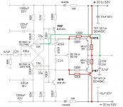
One of the 68K I replaced with 75K multi turn trimmer to get rid of the offset that can be higher value to, whatever you find 100K. If you leave the 68K resistor the BC550C - 560C has to be chosen (matched) accordingly to get the offset close to 0.10mV or so.
I mention that if someone draw a layout to know that is a trimmer.
For simulation you can use 68K.
Greetings gabor
Here is the corrected version
One of the 68K I replaced with 75K multi turn trimmer to get rid of the offset that can be higher value to, whatever you find 100K. If you leave the 68K resistor the BC550C - 560C has to be chosen (matched) accordingly to get the offset close to 0.10mV or so.
I mention that if someone draw a layout to know that is a trimmer.
For simulation you can use 68K.
Greetings gabor
Attachments
comments
if R11 is 1K, it's impossible to get rid of crossover distortion
gain is excessive, NFB lacking, or both
fft looks like a Rio Carnival parade of harmonics
distortion at 1W out is higher than at 57 watts, +/- 30V swing, (onset of clipping)
why R17-R18 are so big? It's neccesary?
if R11 is 1K, it's impossible to get rid of crossover distortion
gain is excessive, NFB lacking, or both
fft looks like a Rio Carnival parade of harmonics
distortion at 1W out is higher than at 57 watts, +/- 30V swing, (onset of clipping)
why R17-R18 are so big? It's neccesary?
Hi
That is bad news.
These is circuit was modified based on Bigun advise and it look like it is wrong..
I post now the one I built and sound excellent but has some thermal drift issues. That was the main reason we modified the VBE and it look like need more work.
Here I post the original circuit , I built it and several other people built it also other. Including some guys from these forum.
If you would like to run a simulation from the original circuit, I will lok it up now
I can see the simulation result, I'm unable to open asc. files with my computer.
Greetings gabor
Attachments
Hi
The previous circuit was built several time and always worked properly.
Now someone who has a lot of experience made a small tweak ( which it make sense to me base on similar circuits)
He get rid of the two 100R resistor and the 2Pc 33p got connected to the VAS.
I did not tested yet these one but I'm sure these is correct!
Why we tied to modified a great sounding amplifier
How I mentioned it had some thermal drift issue.
Greetings gabor
Attachments
Hi Gabor
To open .asc files You need to download and install LTSpice.
Bigun is a very experienced guy, most probably we were not reproducing correctly the mods suggested by him. (something got lost in translation?)
Me myself not an expert in Spice simulation, I'm barely exploring the basics.
Before we continue, we must avoid any confusion, otherwise we are going nowhere. From now on, please refer to the component denomination we are talking about
(R1, C7, Q3, and so on).
The circuit in post #46 is very confusing, it's the same of post #47?
Lastly, if you got an amp actually constructed, that works fine and sound very good, why bother with simulations? rather get it competently measured in the lab bench, and try mods/fine tuning right there.
Hi
Yes Bigun is a very experienced guy, I agree with that. But I have to let you know after I made the suggested mode he did check out the circuit and approved it all do he wrote it may need further adjustment the components values.
The #46 is the original circuit exactly how it was built by me and several other people to, some of them use that amplifier over 10 years period.
If you leave out the red (double power transistors, that need when the PS voltage over 35V or so)
#47 post get a minimalistic modification from a very well experienced guy and totally agree with that.
I will ad component denomination to each components so we avoid the confusion.
Yesterday it was late night when I had the chance to check out these tread.
Greetings gabor
Hi
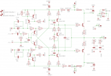
Here is the circuit very identical ( little tweak made by wahab) to the original how was built with one pair power darlingtons.
These should work as good as the original and you can read it better..
All parts has component denomination! C12 is optional only, it is a electrolytic capacitor.
If you could run a basic simulation on these we could compare it with yours.
Thank you very much and sorry for the confusion!
Attachments
Ok, that's it
Thank you Mosquito
I just open up the last schematic you posted and I see you made some mode to.
I do like that! I will have to build these to test it in real life
Any comment or opinion on the simulation result especially compared to the circuit you posted previously
I will install the LTSpice because many times I was unable to open asc. files not just here but all over at the forum.
Thanks for that advice to.
Greetings gabor
I see you already answered to my question... I was on the phone and my time expired meanwhile I tried to edit these post so I reposted again.
Mosquito
Here is a very similar circuit designed by Borys. The original circuit he used Toshiba power mosfets with very good result.
These was modified with the help of Borys so we can use darlington power transistors.
In real life was not tested or built yet ......
Please take a look a the circuit, if you have time and interested maybe run a simulation
Or just take a look it may give you more ideas
Greetings gabor
Attachments
Forget to ask
At the latest circuit you posted R9 & R10 22K value not to high
All other things being equal, performing a .step analisys 22K comes out better than either 18K or 27K.- In the simulation -. This at 1W, 5W and 50W out.
The test bench could tell a different story, or not. "When in doubt, just measure"
Cheers
J.
All other things being equal, performing a .step analisys 22K comes out better than either 18K or 27K.- In the simulation -. This at 1W, 5W and 50W out.
The test bench could tell a different story, or not. "When in doubt, just measure"
Cheers
J.
OK I understood
Thank you for explaining it to meI will build it soon and will se, to me most important the sound of the amplifier and to be stable.
When I listen music I do not care much about the circuit or components etc.
I think most of us think the same way.
The one I built last time sounded far the best what ever I built over the 25 years.
Of course I used special components like PRP resistors, Cardas hock up wires, special wire for signal, 4X 62 000uF capacitors C-R-C connected.
I spend countless hours to find the best VAS transistor to get the best sound.
I still have some original NEC and Sanyo for VAS not tested yet in these circuit.
For the small signal transistor you can use J Fet (all do now hard to find them) like 2SK170BL 2SJ74BL if you have. I did it and I like it with that a bit better. No need for any change in the circuit just turn the J Fet 180 degree and solder it to the place of BC550C & BC560C. To me that give a bit of different sound.
Now I will mode the layout and will test it.
Thank you one more time
Greetings
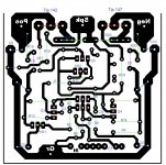
Here we go if someone want to test it..
The VBE transistor goes on the top of the power darlington transistor connected with wires.
J1 is a jumper, these layout was designed for my previous circuit
I think these layout good enough for testing
Please be aware it was not tested yet so look for errors if it has any.
Greetings
The VBE transistor goes on the top of the power darlington transistor connected with wires.
J1 is a jumper, these layout was designed for my previous circuit
I think these layout good enough for testing
Please be aware it was not tested yet so look for errors if it has any.
Greetings
Attachments
Hi
To help you with the layout you mount the PC boards on the heatsink flat.
Similar like these
I draw all my layout by hand with the help of the pain program.
I made some correction and I added some part number what I forget at first time.
The layout look like is good.
The green layout only for help, so you can imagine how you mount the PC boards, otherwise it has nothing to do with these circuit.
Greetings
Attachments

Last edited:
- Status
- This old topic is closed. If you want to reopen this topic, contact a moderator using the "Report Post" button.
- Home
- Amplifiers
- Solid State
- Darlington VSSA