My amp is stable with no load with just the series resistor/induct or combination, R1 and L1 in the pic below. However whenever I try to drive a load (wired up a resistor to output) I get really bad phase margin/oscillations. However, when I try to add the shunt resistor/capacitor the amp goes completely unstable (R2 and C1) in the pic below.
Any ideas why? What components can I try and swap?
Any ideas why? What components can I try and swap?
Attachments
Hi
I think the instability is in the missing components, namely small value resistance 0.33R being typical
on each in this case placed on the transistor collectors. See a Quad 303 output stage schematic with almost identical components where R124, R125 0.33R are provided. There is I know much discussion
elsewhere in the forum concerning best value of these resistors, but 0.33R is likely to be a good starting point. Quad 33 and Quad 303
The Zobel is placed in respect of assistance to the amp to drive a speaker lead, see Post 17
http://www.diyaudio.com/forums/multi-way/190300-best-place-put-zobel-network-2.html
inferring the instability you have is either aforementioned resistors, or possibly the
feedback take off point.The Doug Self many articles on the blameless amplifier would
be a good starting point. http://www.diyaudio.com/forums/soli...gn-book-douglas-self-wants-your-opinions.html
Cheers / Chris
Are you really using a common-emitter output stage on both phases or is that a drafting error?
It's simplistic. I'm really using a CFP output stage with 0.1 ohm emitter resistors. I just am looking to talk about the zobel.
Some discoveries...
I have some spare random inductors around here. Increasing the output inductance from 1uH to ~35uH eliminated the issues of instability when a load is applied. So I guess 1uH inductance is too small, so I'm going to order a bunch of varying inductors from 2uH to 10uH from digikey to try out...
Two, even with the ~35uH inductor I get oscillations when putting the shunt resistor/capacitor on. Still need to debug that.
I had a same problem with one of my early designed amplifier. The root cause was the weak stability of the amplifier. I have to change the compensation in the VAS, to get enough phase margin.
Sajti
Without the shunt resistor/cap I get no overshoot. It seems like my phase margin is good without it.
Unless you can show that it is just the output stage which is oscillating (which is possible with a CFP), then you have to accept that the feedback loop stability is insufficient.
The CR network helps ensure that the output stage sees a resistive impedance at MHz frequencies. However, this is at the cost of seeing a rather strongly capacitive impedance at lower frequencies (100-200kHz) - this may be your problem. Try using a smaller or larger cap than 0.1uF, so the area of maximum phase shift moves up or down.
The CR network helps ensure that the output stage sees a resistive impedance at MHz frequencies. However, this is at the cost of seeing a rather strongly capacitive impedance at lower frequencies (100-200kHz) - this may be your problem. Try using a smaller or larger cap than 0.1uF, so the area of maximum phase shift moves up or down.
Unless you can show that it is just the output stage which is oscillating (which is possible with a CFP), then you have to accept that the feedback loop stability is insufficient.
The CR network helps ensure that the output stage sees a resistive impedance at MHz frequencies. However, this is at the cost of seeing a rather strongly capacitive impedance at lower frequencies (100-200kHz) - this may be your problem. Try using a smaller or larger cap than 0.1uF, so the area of maximum phase shift moves up or down.
I'll do some experiments tonight with, but in theory although without the capacitor I have ~90 degrees of phase margin adding that capacitor is adding another low frequency pole.
Is it just with most designs their dominant pole from cdom is a lot lower than the pole introduced by the zobel cap?
Ok after mucking around with the circuit, it seems like adding a bypass cap to the vbe multiplier eliminates this issue (at least when I have a big cdom). Before I had no bypass cap on the vbe multiplier but I added 0.1uf cap and there is no oscillation when I add the shunt cap/resistor.
The big cdom alone did not help.
Any clue at what is going on here?
The big cdom alone did not help.
Any clue at what is going on here?
With no cap there you get effectively two paths (at higher frequencies) from the VAS to the output, via the two halves of the PP output stage. These will have different phase shifts, because of different source impedance, so you no longer have a minimum phase system. Hence phase shift will be worse than the amplitude response would suggest.
With the cap there you still have two paths but they are now near enough identical (at least at the frequencies of interest, because they both see the same source impedance) so more or less minimum phase.
With the cap there you still have two paths but they are now near enough identical (at least at the frequencies of interest, because they both see the same source impedance) so more or less minimum phase.
With no cap there you get effectively two paths (at higher frequencies) from the VAS to the output, via the two halves of the PP output stage. These will have different phase shifts, because of different source impedance, so you no longer have a minimum phase system. Hence phase shift will be worse than the amplitude response would suggest.
With the cap there you still have two paths but they are now near enough identical (at least at the frequencies of interest, because they both see the same source impedance) so more or less minimum phase.
Can you explain this with some example bode plots with and without the vbe multiplier cap? Hard to grasp.
A system with just one path from input to output will usually be minimum phase. This means you can predict the phase response from the amplitude response, as both arise from a rational polynomial function of frequency.
When there are two or more paths then this is not necessarily true, unless the two paths are identical. The simplest case typically seen is an all-pass filter, which changes the phase while maintaining constant amplitude. Hence two paths often means that you get more phase shift than you would expect from looking at the amplitude response. This can degrade loop stability.
Looking at the typical audio amp (or simple opamp) you can see that one half of the output connects directly to the VAS collector, while the other half connects via the bias sub-circuit. The VAS collector is often a low impedance point (at least for higher frequencies) due to the local feedback from Cdom. Hence the two halves of the output see different source impedances and so will have different frequency responses. Two different paths means non-minimum phase.
Sorry, I don't have any Bode plots up my sleeve - but I'm sure someone has.
So I got my inductors today from digikey.
After using a 4.7u inductor and increasing my cdom a bit (from 68pf to 100pf) I finally got everything rock solid stable into a 8 ohm load. Not quite happy with the slew rate (about 15V/us - was aiming for 20V/us+) but the audio still sounds crisp. Going to mess with the bias current a bit and see if I can increase the slew rate alittle while maintaining stability.
Just goes to show how spice can fool you and you'll never know till you build the circuit.
Hi
Amplifiers have feedback. sometimes both DC and AC, i.e. Signal feedback. Signal feedback is essential. as this is frequency sensitive, this gives rise to instability and even oscillations, when the feedback phase is wrong.
This is altered by the introduction of Zobel network generally changes the feed back characteristic, hence the instability.
What you need to do is play with the values of the capacitor and resistor, to achieve the stability. Better still, keep the zobel network in place and tweak the feedback ac characteristics, not changing the DC characteristic, but this is the more advanced task. do any of the above, or even both, and your amp will stabilize.
Cheers
Nmosfet
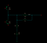
My amp is stable with no load with just the series resistor/induct or combination, R1 and L1 in the pic below. However whenever I try to drive a load (wired up a resistor to output) I get really bad phase margin/oscillations. However, when I try to add the shunt resistor/capacitor the amp goes completely unstable (R2 and C1) in the pic below.
Any ideas why? What components can I try and swap?
There are some suggestions that the VAS capacitor that "bypasses" the Vbe multiplier is better suited to being a high esr electrolytic. It has better damping than the very low esr of a film capacitor.
I can't explain it.Better damping of what? The circuit nodes around there are more likely to look capacitive than inductive so what is there to damp?
I bet you can.
But, there will be some parasitic inductances in and around the VAS and it's current sink and the Vbias circuit with it's two feeds to the output stage.
I have read that any semiconductor that transforms a capacitive output into a negative impedance at it's input could lead to some oscillation/ringing. But maybe my lack of understanding of AC circuit theory has led to me misunderstanding what they were really trying to say.
- Status
- This old topic is closed. If you want to reopen this topic, contact a moderator using the "Report Post" button.
- Home
- Amplifiers
- Solid State
- Adding shunt capacitor and resistor in zobel causes instability - Any ideas why?