In another thread I asked about a substution for the FET in the input stage here, and a general consensus was that a 2SK389 should be fine as long as the servo was tweaked to allow for a larger correction range than the original.
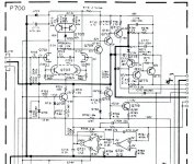
However, the stage is oddly unbalanced... When first powering up, R741 and R743 (the 270-ohm resistors, part of the bias stage) began to get hot enough to smoke. To avoid burning up components whist troubleshooting, I removed Q709, Q715, Q713, Q717, and Q719. Figured at least I could see if the input was doing what it was supposed to.
Here's the deal: The collector of the right-hand side of Q703 is at about 62V as it should be...but the left-hand side is at about 52V.
WTH is going on here? I've been checking other components to see if there are resistors out of tolerance and so forth, but it all looks good. What's more, both channels are displaying the same symptoms....
Attachments
Check the critical matching of R713 and R715 (the 1K res in the emitters of Q705) and the two halves of Q705. Also maybe test or replace Q709/713 to make sure it doesn't have excessively low beta ... (?)
Hummm. But that wouldn't explain why both channels show the same behavior.
Are you sure the inputs are properly grounded?
Good luck!
Eric
Hummm. But that wouldn't explain why both channels show the same behavior.
Are you sure the inputs are properly grounded?
Good luck!
Eric
Q705 is a brand-new 2SA995 dual transistor on both channels...I could see them being a little off, but the differences between the voltages are huge...
Q709/Q713 et al are removed from the circuit to ensure that they are not the problem...stated in first post...")
I'll short out the resistors are see what happens...that won't smoke it, I hope...
BTW, I've pulled out the opamp at one time to see what it did...changed nothing so it was reinstalled.
Q709/Q713 et al are removed from the circuit to ensure that they are not the problem...stated in first post...
I'll short out the resistors are see what happens...that won't smoke it, I hope...
BTW, I've pulled out the opamp at one time to see what it did...changed nothing so it was reinstalled.
Q705 is a brand-new 2SA995 dual transistor on both channels...I could see them being a little off, but the differences between the voltages are huge...
Yes, any small offset or voltage differance between those two fet inputs can cause the unbalance you have.
I'll short out the resistors are see what happens...that won't smoke it, I hope...
Don't worry, as long as the components you mentioned are left out, nothing will smoke.
Dick.
Hi peranders..
I'll short the inputs this evening and see what happens.
Had no choice...the originals were gone...as in, not even in the circuit. Someone before me completely removed them for some reason...and I had to find something that might work... I was suggested to use the 2SK389.Why have you changed the input jfet?
I'll short the inputs this evening and see what happens.
Was out of town for the last four days, so hadn't had a chance to check this thing in any more detail.
I shorted the gates to ground to see WTF happened. Made no difference. The collector on the left side of Q703 is still at about 50V, and the right at about 62V. An ohmmeter shows that the ground is indeed at ground potential, and I measure no difference of potential between chassis ground and the ground line on this board when power is applied.
Then I thought I'd carefully measure the voltages across the two 1K resistors on the emitters of Q705. They look pretty close, but I replaced the 1K resistors with a matched pair anyway. No change. The right hand side of Q705 is obviously saturated, wheras the left side has a good 10-11V from C-E. Also, I measure about -200mV on the emitter of Q703.
Seems like the key is to perhaps rebias Q703, or alter the current source. I can't find anything definately wrong, so I believe it's just that the 2SK389 is simply unhappy in it's new setting. What can I do to balance this thing out??
I know some of you all do this in your sleep...I'd appreciate some ideas on how to make this work....
Hi
But in a previus post you say
So if the transistors are still removed the input stage do not have feedback for balanced DC conditions.
Without feedback the input stage can not be balanced...
Here's the deal: The collector of the right-hand side of Q703 is at about 62V as it should be...but the left-hand side is at about 52V.
But in a previus post you say
However, the stage is oddly unbalanced... When first powering up, R741 and R743 (the 270-ohm resistors, part of the bias stage) began to get hot enough to smoke. To avoid burning up components whist troubleshooting, I removed Q709, Q715, Q713, Q717, and Q719. Figured at least I could see if the input was doing what it was
So if the transistors are still removed the input stage do not have feedback for balanced DC conditions.
Without feedback the input stage can not be balanced...
But if I put the transistors in, Q713 and Q717 are turned on so hard that R741 and R743 will go up in smoke. Which is why they were removed....to see why the input stage is driving these transistors so hard and make sure that they were not influencing it.
The collectors of Q717 and Q719 go to the heatsink mounted bias transistor..which will at least pass a diode test. Is it possible that the bias pot was turned up so high that it was trying to smoke these resistors? I wouldn't think that it would be capable of that range. Still, I have turned the pot to zero ohms in preparation of reinstalling the transistors in this amp section, so the bias transistor should be cut off.
Feedback may be necessary to balance the stage perfectly, but is it really necessary in order to get it to within a volt or two? You are the first to suggest this... 10+ volts is a lot of imbalance.
I also think the offset with R701 and R731 shorted is remarkably high.
Assuming a ln(2)*kT/q~=18mV offset between the bases of Q703, which is nearly worst-case, one could expect a collector current of about 2mA on one side and 1mA on the other side. If each of the two PNP's on top has an emitter current of 1.5mA, one of them will saturate, since its collector current is only about 1mA. The remaining 0.5mA will flow through the diode and one of the 10kohm resistors. Together with the 1.5mA from the other PNP, you end up with the 2mA flowing into the other half of Q703.
So far so good, but with 0.5mA flowing through one 10kohm resistor, I'd expect about 5V of offset, not 12V. Maybe analysing it more accurately can get the theoretical figure up to 6V or 7V, but 12V?
I would check the connections between Q703 and the PNP's and the voltages at the bases of Q703. If you can't find anything wrong with Q703's connections, you could also try connecting 100 ohm resistors directly in series with the bases of Q703 and directly in series with the gates of the FET's, as close to the transistors and FET's as possible. That could help if your amplifier is suffering from parasitic oscillations. Parasitic oscillations often cause weird biasing and/or smoke.
By the way, I wouldn't worry about the -200mV at the emitters of Q703. That can simply be due to the different JFET's.
I can accomplish the same thing by removing the opamp, since it is socketed. It changes nothing. Also consider that the response of the servo is very slow...for it to result in such a mismatch (if it were the cause) would take a bit of time, but the imbalance is there immediately on power up.Tube_Dude said:Try to disconnect R 753 - 100k from the servo...as there are no feedback the servo is trying hard to produce the balance...but it is "blind" as there are no feedback from the output of the amp.
For the hell of it, I checked the voltage directly between the sources of the FET (and thus the bases of Q703). It measured about 8mV. The connection between the collector of Q703 and the collector of Q705 is a rather short run of foil on the PC board...looks fine and measures fine.MarcelvdG said:I also think the offset with R701 and R731 shorted is remarkably high.
I would check the connections between Q703 and the PNP's and the voltages at the bases of Q703.
The scope doesn't show oscillations, and there is no room to add a resistor...not even as a test. The components and the foil traces were obviously made as short as possible.If you can't find anything wrong with Q703's connections, you could also try connecting 100 ohm resistors directly in series with the bases of Q703 and directly in series with the gates of the FET's, as close to the transistors and FET's as possible. That could help if your amplifier is suffering from parasitic oscillations. Parasitic oscillations often cause weird biasing and/or smoke.
Is the problem the choice of FET? Is the 2SK389 just plain unsuitable for this circuit?
As an aside...wanted to remind that both channels exhibit the same behavior. If there was a component failure, I'd think that it would be unlikely that it would do the same thing on both channels. The only thing common to both channels is the supplies (+/-15V and the +/-66V) which look fine, and the ground rails, which also look fine.
Seems like...if a design failure (poor component choice for the job at hand) then the problem would be common to both channels as we see. A component failure would much more likely to show some major difference between each channel.
Is my logic flawed?
Seems like...if a design failure (poor component choice for the job at hand) then the problem would be common to both channels as we see. A component failure would much more likely to show some major difference between each channel.
Is my logic flawed?
The Saga of the missing transistors...
One thing i repeat!!
The input stage can not be balanced with the servo connected...and the LTP without DC feedback from the VAS stage!
Try to put the missing transistors and slowly increase the voltage of the amp with a variable DC power supply...watching for the current and heat in the components...
What type is Q703? Do you know its maximum offset specification? So far, I've implicitly assumed its offset (DELTA VBE at equal collector currents) to be negligible compared to the offset of the JFET pair, but perhaps that's wrong.
If you connect a potmeter (100kohm...250kohm or so) between the +15V and -15V, and connect its wiper to a 12kohm resistor, with the other side connected to R731, can you manually get the stage balanced? If so, does the bias point change significantly when you touch nodes of the circuit with an isolated screw driver?
If you connect a potmeter (100kohm...250kohm or so) between the +15V and -15V, and connect its wiper to a 12kohm resistor, with the other side connected to R731, can you manually get the stage balanced? If so, does the bias point change significantly when you touch nodes of the circuit with an isolated screw driver?
My regular workload is really screwing with my ability to reply in a timely manner, but I truly appreciate the suggestions that you all are giving me.
I connected a 100K pot to the +/-15V supply, and a 12K resistor to the 120-ohm resistor connected to the gate of the right side of the FET. I made sure that the applied voltage started off as something negative...didn't want to forward bias the FET.
What I discovered was that...with +8mV on the gate of the right FET (still negative with respect to the source since the source is at about 350mV) the thing is balanced. That would correspond to about 800mV output from the opamp...
OK..now I get to act (not really an act) real stupid....what does this tell me? Tube-Dude is right? I must put the transistors in for it to balance?
I checked the continuity of the line that runs to the output from the opamp to ensure that it was OK, and also checked the resistors in the opamp circuits. All looks OK.
So...time to put the transistors in and see what smokes??
I feel like this thread is the forum equivalent of a auto wreck: everybody stops to take a look, but only a handful offer any help.
I'd really not like to smoke any more parts...was hoping to get some suggestions now that I know it can balance with an external pot...
TIA....
I'd really not like to smoke any more parts...was hoping to get some suggestions now that I know it can balance with an external pot...
TIA....
rubberneckers
I think we rubberneckers WANT to help, but are a bit mystified because we are all thinking about circuit mismatch sources and then keep suddenly remembering that you said the same thing occurs in both channels.
With the 8 mV offset applied to the right FET, what are the voltages at the FET sources (BJT bases)? Are those also different by about 8 mV?
- Status
- This old topic is closed. If you want to reopen this topic, contact a moderator using the "Report Post" button.
- Home
- Amplifiers
- Solid State
- FET input stage problems