Another possible cause of failure although I don't know how common, is through someone increasing the Iq. In that regard r641 and r643 the 910R resistors from the driver emitters are not crossed coupled to each other but to the opposite voltage rail. There is a recent instance of failure due to excess heating, of driver stage components.
Indeed, particularly if they are inadequately heatsinked.
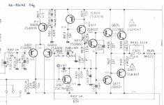
However, just to clarify things: I have been working on an RA-820AX (power amp part schematic enclosed), which is quite different to the more complex RA-820BX4 that ostripper commented on.
But I agree with ostripper's views on the strange design topography of the BX4 - and interestingly, its specs are for a much poorer THD - between 0.1% and 0.3% - or ten times the 0.03% of the AX.
Ok, I know that THD is not the only indicator of an amp's qualities - but still...
Attachments
I thought transistors were "three legged fuse protectors".
Craig
LOL
Rotel RA-820AX 2nd stage mod
Looking back at the encouraging results from stage 1 - I find it pretty cool that by (net) removing of three components from an RA-820AX (and a bit of rearranging, recalculations and replacings) you can actually improve THD performance with 10dB.
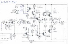
Bearing in mind that in the rules of the wager I was "banned" from changing any of the Rotel design topography in the power amp audio path, so the 2nd modification stage therefore was set to further steady the current supply to the input and VAS stages by improving the ripple on the DC rails.
First by filtering the input stages' positive and negative supply rails with two 100ohm/100uF/100nF lowpass RC filters and then inserting a cascode transistor in the tail-current source using the filter mod from stage 1.
Does this work? - You bet.
Stage 2 results:
Input stage rail ripple:
Reduced from 30mVac to less than 8mVac
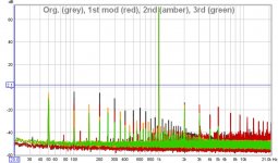
A large reduction in the higher harmonic peaks, THD down to 0.0086% - hey, that is now better than e.g. the Linn Majik specs!
THD+N now dramatically down to 0.0203% but the noise reduction still appeared only on the even 50Hz harmonics, while the odd 1st (50Hz), 3rd (150Hz), 5th (250Hz), etc. - seemed practically unchanged.
Again, these peaks may actually not be coming from the amp, but probably caused by our imperfect RTA measurement setup.
Anyway, there is still quite some way down to the 0.003% THD target - and I am now quickly running out of allowable options.
But.... can it be done? ..... will I win the bet? Ta da daaa...
Stay tuned for the 3rd mod post!
Looking back at the encouraging results from stage 1 - I find it pretty cool that by (net) removing of three components from an RA-820AX (and a bit of rearranging, recalculations and replacings) you can actually improve THD performance with 10dB.
Bearing in mind that in the rules of the wager I was "banned" from changing any of the Rotel design topography in the power amp audio path, so the 2nd modification stage therefore was set to further steady the current supply to the input and VAS stages by improving the ripple on the DC rails.
First by filtering the input stages' positive and negative supply rails with two 100ohm/100uF/100nF lowpass RC filters and then inserting a cascode transistor in the tail-current source using the filter mod from stage 1.
Does this work? - You bet.
Stage 2 results:
Input stage rail ripple:
Reduced from 30mVac to less than 8mVac
A large reduction in the higher harmonic peaks, THD down to 0.0086% - hey, that is now better than e.g. the Linn Majik specs!
THD+N now dramatically down to 0.0203% but the noise reduction still appeared only on the even 50Hz harmonics, while the odd 1st (50Hz), 3rd (150Hz), 5th (250Hz), etc. - seemed practically unchanged.
Again, these peaks may actually not be coming from the amp, but probably caused by our imperfect RTA measurement setup.
Anyway, there is still quite some way down to the 0.003% THD target - and I am now quickly running out of allowable options.
But.... can it be done? ..... will I win the bet? Ta da daaa...
Stay tuned for the 3rd mod post!
Rotel RA-820AX 3rd stage mod
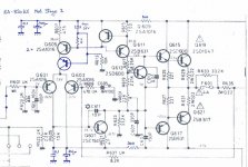
3rd and last mod stage was therefore on the large reservoir capacitors. Rotel uses Rubycon 6800uF's that at first measured sort of ok, with decent low ESR and capacitance only down to 6200uF, probably still within specs. However, Rotel has often had the habit of placing the reservoir capacitors so the 0Vdc pins go to the ground star point on the PCB. This is a known bad idea considering the large charging currents that go through these caps.
The budget allowed replacing the Rubycon's with two standard 10,000uF, low ESR, 105oC Panasonic types. I placed them pins-up, attaching the flat tops down to the PCB with a high strength silicone. Then the pins were connected directly to the bridge rectifier's + and – pins and the ground transformer return pin respectively, with equal lengths of heavy wires.
This is the right way to do it – check out the results:
The 100Hz noise peak dropped another impressive -15dB, making the total 100Hz reduction by these mods over -32dB! That is a staggering 97% reduction from what was maybe a faint audible speaker hum - to absolute dead silence! Even the 50Hz and its odd harmonics finally dropped 5-8 dB.
So, the 3rd mod results:
Input rail ripple down below 5mVac
THD+N value staying at 0.0209% - a bit strange given the above clear improvements
THD now at 0.0039% - aaaghh, so close!
So, I expected to have lost the bet, but before conceding defeat I had yet another look at the RTA setup, particularly the ASUS Xonar U7 USB soundcard we used as front-end. In addition to the 50Hz noise pickup even in a direct loopback there were small visible signals at 1kHz, 2kHz and 3kHz, probably from some internal oscillator circuitry, I don't know.
However, I re-measured the 820AX using a 900Hz instead of the standard 1kHz test tone, and bingo – I got a THD value of 0.0029% Yes! - I won (of course ignoring all mutterings about cheating, etc.)
Also, I then put our best digital storage oscilloscope on the amp output and sync'd the trigger to Line in order to look for the supposedly large 50Hz noise signal – Nothing, zilch – nada!
It must therefore be a measurement artefact in the Xonar U7 setup, and therefore the THD+N is probably better than the last measurement would indicate.
It is times like this you wish you had a GBP 10,000+ Audio Precision RTA ready on the shelf! If anyone interested has one available near Stansted, UK – please do get in touch.
Enclosed are the staged power amp circuitry mods with the resulting comparative spectrum chart showing how Mod 1 “shaved off” the grey distortion peaks, Mod 2 the red and Mod 3 the amber – resulting in the respectable green spectrum.
It is always tempting to carry on modding to try further shaving of the remaining distortion peaks – but also important to know when to stop soldering and start listening - which is next.
Attachments
20 or more years ago now a friend upgraded his system with an early 820 model. His system included some super loudspeaker cable which caused a major failure soon after switching on. A loud hum followed by silence. The replacement also hummed but my friend reacted quickly to turn it off in time.
The cables were junked and the amplifier was O.K. with normal cable. I was unconvinced by this as the amplifier was only marginally stable. You are saying you have had dozens of Rotel amplifiers to repair which raises another question about reliability and whether there is a connection between these two considerations.
I should like to think that Rotel made modifications to the circuit accordingly, but I have my doubts. What can you tell us in that regard.
Hi mjona,
Some times a shop will see quite a high number of a certain model of equipment if it happened to sell extremely well in that area. This doesn't always mean that there is a problem with the design of that model, but a small issue could then really inflate the number the local repair guy sees.
We have all seen some specific loudspeaker cables that had very high capacitance as well. The victims all had to spend enough money on speaker wires to make them prey. If the phase margin was also a little low, that might be all that was needed. The manufacturing fault in this case isn't as horrible as it first appears.
-Chris
Hi AngelP,
I am curious about two things. I haven't worked this out yet, but can you be certain that the tail current was not changed by modification #1? Did you monitor the voltage across R607? Also, why didn't you leave the diodes in circuit? They would have made a very low impedance load to any AC ripple that got through the filter you installed. I would think that performance would have been increased. You might have had to block the light from hitting the diode junctions.
If you did match Q601 and Q603 closely, it will make an audible difference if they were not originally matched very well. The improvement can be dramatic in fact. Also, tie those transistors together so they will track temperature better. I use heat shrink tubing and heat sink grease.
Otherwise, you did a really good job of plotting your changes for everyone. Nicely done!
-Chris
Hi mjona,
Some times a shop will see quite a high number of a certain model of equipment if it happened to sell extremely well in that area. This doesn't always mean that there is a problem with the design of that model, but a small issue could then really inflate the number the local repair guy sees.
We have all seen some specific loudspeaker cables that had very high capacitance as well. The victims all had to spend enough money on speaker wires to make them prey. If the phase margin was also a little low, that might be all that was needed. The manufacturing fault in this case isn't as horrible as it first appears.
-Chris
My friend told me the transformer in his amplifier had burned out after setting up in his system straight out of the box.
20 or more years ago now a friend upgraded his system with an early 820 model. His system included some super loudspeaker cable which caused a major failure soon after switching on. A loud hum followed by silence. The replacement also hummed but my friend reacted quickly to turn it off in time.
The cables were junked and the amplifier was O.K. with normal cable. I was unconvinced by this as the amplifier was only marginally stable. You are saying you have had dozens of Rotel amplifiers to repair which raises another question about reliability and whether there is a connection between these two considerations.
I should like to think that Rotel made modifications to the circuit accordingly, but I have my doubts. What can you tell us in that regard.
Hi mjona,
Yes, I can readily believe that could/would happen.
The RA-820AX is different, as Rotel for some philosophical or marketing reason decided to remove the output inductors (the large spooled copper wire components usually found on power amp PCB's) AND they also omitted the Zobel networks (the 100nF/10ohm series pair from amp output + to GND).
The inductor is a tried and tested method of protecting the amp against capacitive loads (actually sometimes loads as low as 100nF can make an amp without it start to oscillate) and the Zobel protects against oscillation caused by complex or excessive inductive loads.
Warning! - Never connect an electrostatic speaker to a Rotel amp of this age - or do so at your peril and pray that the amp blows before your expensive speakers!
(yeah, ok I will now be flooded with "I have used this amp with my Quads for years without any problems..) and that's fine, living on the edge of instability can be fun - just don't tell you bank manager).
Electrostatics(Quad's etc.) pose a significant capacitive load - actually in the uF range. But even attaching "normal" speakers through "fancy" cables (braided etc.) that may also be too long or coiled up or bi-amped or whatever could quite possibly cause the disaster you describe - even on a Rotel straight out of the box.
The 820AX's only output defence is a pair of 0.22ohm/2W wirewound resistors (R635/6) and the 4A/0.1ohm fuses in series with the output. Ok, they are placed within the feedback loop, but they still produce an unwanted reduction in damping factor, and... - no, don't get me started.
Hi AngelP,
I am curious about two things. I haven't worked this out yet, but can you be certain that the tail current was not changed by modification #1? Did you monitor the voltage across R607? Also, why didn't you leave the diodes in circuit? They would have made a very low impedance load to any AC ripple that got through the filter you installed. I would think that performance would have been increased. You might have had to block the light from hitting the diode junctions.
If you did match Q601 and Q603 closely, it will make an audible difference if they were not originally matched very well. The improvement can be dramatic in fact. Also, tie those transistors together so they will track temperature better. I use heat shrink tubing and heat sink grease.
Otherwise, you did a really good job of plotting your changes for everyone. Nicely done!
-Chris
Hi anatech,
Thank you for your questions and comments.
I removed the diodes mainly because I needed the PCB real estate for the mod components. Further, if you look at the original schematic, the VAS current source transistors Vbe-drop does the job nicely as the dc voltage on the basis of Q611 is only 100mV lower than that of Q605 basis.
Also, in one sweep I could filter both current sources - and have blackened p-n junctions! (Not that we worry much about that over here, as the sun so rarely shines in the UK
 )
)Ok, I admit that the tail pair current did probably change a little - also because I decided to pull Q605 when I upgraded to the cascode pair - as Q605 too would have had suffered reverse Vbc current due to the open R611.
I fully subscribe to your comment about the importance of matching of the input tail pair betas.
(In fact I did measure one pair of the old 2SA1016's and they were both low and severely out in hFE (234 vs. 175). But I guess that could be due to the reverse current damage?
Also, my audio TO92 PNP inventory mainly consists of a tape reel of factory purchased Fairchild 2SA992F, from which I pick out nicely matched devices.
I will post a picture of the PCB showing the mods, I simply use superglue to tie the TO92 pairs together - quicker, easier and less messy. Does the job, the offset stays rock solid even when blowing cold air over the trannies.
Oh, BTW, I also fully subscribe to your wife's proverb - could I get a royalty free licence to use that?
Nice work. Since you are focusing on 50 hz (among other things) have you checked shielding and covers. I ask, because I had a preamp with hum, which went away as soon as it was buttoned up and all the covers put on. Sometimes shielding wires (or twisting with ground leads) can help.
AngelP, that's a first-rate job of applying a few basic engineering principles in just about the simplest manner possible to get a stunning result.
I wonder if the original designer is still around to see your mods and then go bang his head into a wall.
Thank you for the kind words, Russell
I have absolutely no bones to pick with the original designer. May his/her head hold strong and the wall break. I would have loved to put the commercial success of the design on my CV!
I mean, would I have been able to boldly stand up to senior design and marketing managers and propose these mods 30+ years ago? No.
At that time I was but a young electronic engineer with a few successful designs under my soldering iron. And probably also pretty gullible to all the strange audio-hype ideas that were floating around in those days.
Experience is something that creeps up on you - and when you realise that you have it, you know you're getting old.
Nice work. Since you are focusing on 50 hz (among other things) have you checked shielding and covers. I ask, because I had a preamp with hum, which went away as soon as it was buttoned up and all the covers put on. Sometimes shielding wires (or twisting with ground leads) can help.
Thank you sregor, good point.
I did go through the trouble of putting the bottom cover back on between measurements, but not the top. Anyway, the top was also off when I eventually put the scope on and found no measurable 50Hz.
It is some measurement artefact in the RTA setup and it really irks me. I've tried using a shielded battery powered laptop with the Xonar U7 - same result. Any ideas?
Hi mjona,
Yes, I can readily believe that could/would happen.
The RA-820AX is different, as Rotel for some philosophical or marketing reason decided to remove the output inductors (the large spooled copper wire components usually found on power amp PCB's) AND they also omitted the Zobel networks (the 100nF/10ohm series pair from amp output + to GND).
I did note the absence of the inductor and zobel but left that unsaid - the 0R22 output buffer resistor too. There was probably a reliance on cables having suitable inductance. Naim have a caveat about using their branded cable accordingly - going so far as to specify a minimum length of 2.5 metres. Naim cable and the wire is thick and rigid which can pose some problems with lightweight speaker and outlet terminals.
I think it would be informative in terms of your caveat - in the absence of any homework from Rotel - to know how much inductance is needed for the Rotel 820 to be stable with a typical two way box speaker using standard wire types - either figure 8 or twisted lengths of separated ones. Or, how much capacitance in parallel with 8R is tolerable without causing disruption to a 10 kHz square wave and how much inductance is needed to negate that when the boundaries are pushed.
Hi mjona,
I had seen many amplifiers that had cracked connections around the bias transistors before wave soldering got the attention it needed. Higher thermal mass and attachment to heavy unsecured objects meant that many connections didn't wet properly. So that could have been the root cause as well. Brands like Luxman had receivers that would melt the plastic feet in the showroom. The bias current left the factory way too high. Of course, as your friend observed, full blown oscillation can be pretty destructive as well.
Naim stuff? Not impressed at all. Very overpriced to start with, and nothing even technically interesting going on. Cyrus on the other hand does have what I would call advanced designs. Their boxes are too small, even though they are very capable products.
-Chris
Now that inspires confidence!My friend told me the transformer in his amplifier had burned out after setting up in his system straight out of the box.
I had seen many amplifiers that had cracked connections around the bias transistors before wave soldering got the attention it needed. Higher thermal mass and attachment to heavy unsecured objects meant that many connections didn't wet properly. So that could have been the root cause as well. Brands like Luxman had receivers that would melt the plastic feet in the showroom. The bias current left the factory way too high. Of course, as your friend observed, full blown oscillation can be pretty destructive as well.
Naim stuff? Not impressed at all. Very overpriced to start with, and nothing even technically interesting going on. Cyrus on the other hand does have what I would call advanced designs. Their boxes are too small, even though they are very capable products.
-Chris
I've followed this thread to because I also modded an RA820A some years ago. There seem to be a lot of versions of this amp too. Mine is the RA820A and one stand out feature is the high gain it runs, a 33k and 470 ohm feedback network. The board layout isn't optimal (the reservoir cap grounding issue) and so there is always faint hum.
My approach was very different... and just for fun,
http://www.diyaudio.com/forums/soli...l-ra820a-use-hexfetss-amongst-other-mods.html
because I also modded an RA820A some years ago. There seem to be a lot of versions of this amp too. Mine is the RA820A and one stand out feature is the high gain it runs, a 33k and 470 ohm feedback network. The board layout isn't optimal (the reservoir cap grounding issue) and so there is always faint hum.My approach was very different... and just for fun,
http://www.diyaudio.com/forums/soli...l-ra820a-use-hexfetss-amongst-other-mods.html
Hi AngelP,
I am not being critical of what you have done at all. Just one tinkerer comparing notes with another. Your circuit changes show you were certainly on the ball when you designed these changes. The measured distortion vindicates your choices as the amp will probably sound better. Not because it measures better, but because you addressed a few problems.
The 2SA992F parts are better suited to input transistor duty. Yes, the original pair was probably damaged from reverse bias due to the offset. It's great that you have them on tape. Matches are certainly easier to find, and you can mark the Hfe by each part, testing once.
The only reason I don't use superglue is that it can be messy (so can grease), and it dries out quickly. I may try using it in the future again though. You just showed everyone that you know exactly what you are doing. I am looking forward to seeing your completed work!
Why, absolutely!
It fits soooo many situations.
-Chris
True enough. I wonder how much signal modulation there might be doing this? You would have to monitor the tail current to find out. For CCS use, I'm one of those guys who enjoys putting red LEDs to use. The smaller ones fit through the hole in a TO-126 transistor, so that can buy you some temperature stability. The higher resistance needed to keep the tail current the same would possibly make the cascode transistor unnecessary. Thoughts, or have you ever compared this with what you have designed?if you look at the original schematic, the VAS current source transistors Vbe-drop does the job nicely as the dc voltage on the basis of Q611 is only 100mV lower than that of Q605 basis.
I am not being critical of what you have done at all. Just one tinkerer comparing notes with another. Your circuit changes show you were certainly on the ball when you designed these changes. The measured distortion vindicates your choices as the amp will probably sound better. Not because it measures better, but because you addressed a few problems.
The 2SA992F parts are better suited to input transistor duty. Yes, the original pair was probably damaged from reverse bias due to the offset. It's great that you have them on tape. Matches are certainly easier to find, and you can mark the Hfe by each part, testing once.
The only reason I don't use superglue is that it can be messy (so can grease), and it dries out quickly. I may try using it in the future again though. You just showed everyone that you know exactly what you are doing. I am looking forward to seeing your completed work!
could I get a royalty free licence to use that?
Why, absolutely!
It fits soooo many situations.
-Chris
I take it you're going out of the U7, into the amp, out of the amp into an attenuator, and back into the U7's line in, or something along those lines, right?It is some measurement artefact in the RTA setup and it really irks me. I've tried using a shielded battery powered laptop with the Xonar U7 - same result. Any ideas?
That's a big fat ground loop right there, which I suspect may be picking up things inductively in this case. I suggest you place the attenuator right at the speaker output and otherwise minimise loop area as far as possible. A resistor of about a kOhm in the ground connection either input or output wise is also worth a shot.
I would definitely look into Zobel network etc. for the next step. Using 0R22s was an el cheapo solution.
Last edited:
- Home
- Amplifiers
- Solid State
- Improve a Rotel amp THD by 20dB!