Not sure this makes much sense...or if asked before.
But how close should the DC voltage from the + rail and the - rail mirror each other? If measuring from emitter resistors. What is acceptable difference?
If there is no oscilloscope, to physically see clipping on + or - side. But measurements on both side vary 10-20mV difference.
I read that clipping can occur on either + or - side, if the voltage is not close enough. And cause the amp to not perform as should. Or loss of sound quality.
Hi,
Clipping depends on how closely the output can approach
the rails. Often this is assymetric, e.g. 1V for one rail and
2V for the other, so rail matching is a rather moot point.
I wouldn't worry about the issue at all in a practical amplifier.
Symmetry of the power supply will mean they are near enough.
rgds, sreten.
Hi,
With no load the currents should be the same.
That implies a output DC offset of 12mV,
assuming the resistors are exactly equal,
and each one is dropping 61mV.
rgds, sreten.
How did you calculate an Offset? What is the formula?
Edit: .061 divided by .47 = 12.9mV If im right
I will go back and recheck the DC offset, it my have swayed. Also the resistors or original and may have also.
Last edited:
How did you calculate an Offset? What is the formula?
Hi,
Assuming the resistors are equal with no load they
much have the same current and hence voltage drop.
49mV + 73mV = 122mV which is 61mV for each.
Which implies output offset is 12mV.
If your literally measuring across the resistors
then the numbers imply poor value matching.
rgds, sreten.
Last edited:
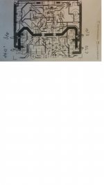
Aha, that makes sense now, though with complementary FET outputs, those are technically "source resistors." But with common BJT outputs, emitter resistors are fully understood now that I see the circuit.Measured here in red
These measurements probably have little or nothing to do with the power rail voltages. Each or both rail voltages could probably vary a bit without making a change here.
On to other observations:
I agree with this, but I wonder if the OP has a load on the amp (as in a speaker connected). That would explain the large difference in these measurements, with the difference created by the load.Hi,
Assuming the resistors are equal with no load they
much have the same current and hence voltage drop.
I don't think you can get the offset voltage with what we know. You can calculate the current through the top and bottom resistors, and the difference will be the current through the output (as the rest of the circuit has high enough resistance to draw negligible current), but the offset voltage would be the difference current divided by the load's DC resistance.49mV + 73mV = 122mV which is 61mV for each.
Which implies output offset is 12mV.
If your literally measuring across the resistors
then the numbers imply poor value matching.
rgds, sreten.
Or it would be whatever the OP measures between the output terminal and ground.
Hi Guys
Supply voltages are measured with respect to ground only. Their symmetry is not critical except to symmetric clipping, or if idle currents will vary with them.
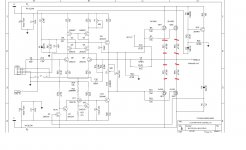
The post-13 schematic notation shows that the voltage being measured is across the source resistors of the output mosfets. This voltage is called Vq - quiescent voltage - and indicates the current through the mosfet using Ohm's law and the resistor value.
Where one would expect the currents through the upper and lower devices to be the same, they might not be. One of each pair (ns or Ps) might take a bit more or less current based on its effective gain, or transconductance. This is something that can be tested prior to building, and "close" devices selected. Usually the total current for the sides will be the same, but this can be offset depending on what other parts of the circuit take or add current from the output node - there is nothing like that in your circuit.
If there is a DC offset at the output node, this can be caused by many reasons, few of which relate to the idle current of the amp.
Have fun
Supply voltages are measured with respect to ground only. Their symmetry is not critical except to symmetric clipping, or if idle currents will vary with them.
The post-13 schematic notation shows that the voltage being measured is across the source resistors of the output mosfets. This voltage is called Vq - quiescent voltage - and indicates the current through the mosfet using Ohm's law and the resistor value.
Where one would expect the currents through the upper and lower devices to be the same, they might not be. One of each pair (ns or Ps) might take a bit more or less current based on its effective gain, or transconductance. This is something that can be tested prior to building, and "close" devices selected. Usually the total current for the sides will be the same, but this can be offset depending on what other parts of the circuit take or add current from the output node - there is nothing like that in your circuit.
If there is a DC offset at the output node, this can be caused by many reasons, few of which relate to the idle current of the amp.
Have fun
Aha, that makes sense now, though with complementary FET outputs, those are technically "source resistors." But with common BJT outputs, emitter resistors are fully understood now that I see the circuit.
So are those emitter resistors?
No load.I agree with this, but I wonder if the OP has a load on the amp (as in a speaker connected). That would explain the large difference in these measurements, with the difference created by the load.
So the measurement of offset is still best measured at the speaker outputs.I don't think you can get the offset voltage with what we know. You can calculate the current through the top and bottom resistors, and the difference will be the current through the output (as the rest of the circuit has high enough resistance to draw negligible current), but the offset voltage would be the difference current divided by the load's DC resistance.
Or it would be whatever the OP measures between the output terminal and ground.
- Status
- This old topic is closed. If you want to reopen this topic, contact a moderator using the "Report Post" button.
- Home
- Amplifiers
- Solid State
- How close should the +/- rails mirror each other