100K dual audio taper
or 220K dual LINEAR with shunt on wiper ~47K see here ESP - A Better Volume Control
better tracking on linear pots
> The other advantage of the 'fake' log pot is that linear pots usually have better tracking (and power handling) than commercially available 'log' pots, so there will be less variation in the signal between left and right channels. This is improved even further by the added resistor, which will allow a cheap carbon pot to equal a good quality conductive plastic component (at least for accuracy - I shall not enter the sound quality debate here).
the hardest part is finding a mechanical fit with hopefully dual shafts.
option 1 100K audio taper pot with twin cntrols, audio tapers usually have poor channel-channel tracking, the twin shafts let you manually adjust to correct this. the tradeoff is > at each volume level the level will be mismatched. BTW the original had a custom taper > if you notice the tap has its own resistance built in its trace length also in series with an external 10K, so some calibration was possible by the OEM> this wont be the case with a replacement so the problem will be unique to whatever new part you select. ( FWIW audio taper is usually pretty bad that's why custom 4 pin parts existed in 1st place )
option 2 faking a linear taper > since this requires a shunt on the wiper usually 10:1. This requires a higher value linear pot since the shunt is now in parallel. So looking at the highest position, the load on preceding stage is now ~220K // 22K . then as a compromise use 47K shunt. IMO using a simple calibration and modifying one shunt can give the closest tracking hassle free for life.
also 22K shunt may also be used b/c its rare to set the gain at maximum so loading isn't severe as worst case above.
Last edited:
Unfortunately the concentric pots proposed and other ones I found on Ebay do not match the dimensions of the OEM pot. Bummer.
So really that leaves us with option 2 i.e. linear 220K with a shunt 47K resistor to fake log law. I was thinking of using a trimpot for the shunt resistor to do the 1-off calibration you were talking about to improve tracking between channels. 27 turn 100K trimpot should be good.
Thanks infinia I think i understand, it's 220K//47K so as to maintain the input impedance / loading of the preceding stages. Makes sense.
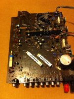
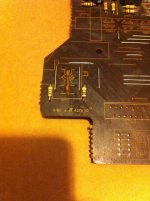
FWIW I measured the resistance of the carbon track for the tap and that was in the ~200 ohm range, which is not much compared to the 10K resistor after the tap point in the original OEM setup.
So really that leaves us with option 2 i.e. linear 220K with a shunt 47K resistor to fake log law. I was thinking of using a trimpot for the shunt resistor to do the 1-off calibration you were talking about to improve tracking between channels. 27 turn 100K trimpot should be good.
Thanks infinia I think i understand, it's 220K//47K so as to maintain the input impedance / loading of the preceding stages. Makes sense.
FWIW I measured the resistance of the carbon track for the tap and that was in the ~200 ohm range, which is not much compared to the 10K resistor after the tap point in the original OEM setup.
Last edited:
As to those ceramics the schematic makes it look like they are shorted across the ground, maybe the are tying two ground points to shunt RF, I would only change them to ceramic NPO/COG or silver mica if thats the case...
That would be a good explanation but I don't understand why have chosen to join the 2 grounds right where the pot is - there's plenty of space elsewhere on the board.
The original pot has a 9th leg connecting the pot case to pcb ground, so maybe the purpose of the capacitors is to decouple the pot from pcb ground?
Last edited:
MADE IN JAPAN ALPS 16mm 100K DUAL LINEAR CONTROL POT WITH LOUDNESS TAPER | eBay
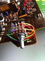
That's the pot I ended using up - very similar to the original part but to be honest could have used any standard lug type.
That's the pot I ended using up - very similar to the original part but to be honest could have used any standard lug type.
Last edited:
Okay question for the experts...
I have been thinking... given the difficulties finding the right pot with loudness taps these days, would it be possible to ...emulate loudness taps by means of resistors soldered on the CW & CCW legs of a normal 3 pin pot?
See attached sketch to see what I mean. The pots are 100K in both cases.
I guess another option for the emulated pot could be a 100K pot with 30K & 20K resistors (more loudness effect) or even 120K & 80K resistors (less loudness effect)?
Would it work?
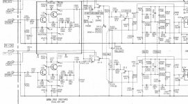
The Sony STR-313 receiver from the late seventies had a switchable loudness circuit without using a tapped volume potentiometer. Trying to attach this part of its schematic ...
Attachments
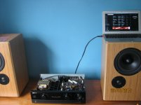
She sings beautifully!! What a great little amp 
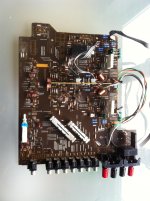
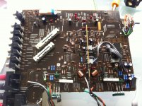
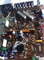
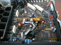
The replacement linear ALPS pot worked a treat. Panasonic FC for most places and Nichicon for recapping are always a good choice. I used EPCOS (TDK) for the main filter ones this time, they're great... plenty of kick!
The replacement linear ALPS pot worked a treat. Panasonic FC for most places and Nichicon for recapping are always a good choice. I used EPCOS (TDK) for the main filter ones this time, they're great... plenty of kick!
Attachments
Last edited:
She sings beautifully!! What a great little amp
The replacement linear ALPS pot worked a treat. Panasonic FC for most places and Nichicon for recapping are always a good choice. I used EPCOS (TDK) for the main filter ones this time, they're great... plenty of kick!
Nice,now let all the tweaks burning in for 2-3 months maybe more and you are fine.

Volume control
Hi Chatziva,
I have the same trouble as you did and have managed to get hold of the same vol control.
Did you just do a simple wire from circuit board to control. I also notice from your photo a wire going from pin 9 at the back, i presume this is soldered onto the rear of the vol control.
Any comments or updates please.
Mike
- Status
- This old topic is closed. If you want to reopen this topic, contact a moderator using the "Report Post" button.
- Home
- Amplifiers
- Solid State
- Pioneer A400 Volume Pot Replacement