Here is the scenario,
I am looking for a simple circuit to recreate this I have had a few ideas however I though I would ask the question.
The problem is a tube based situation, however the answer is SS.
Simple circuit that works.
This is feeding a tube heater circuit that have low resistance before warm up. The power supply trips on current limit and requires a soft start. Easy.
OK.
Existing is an NTC at 160 ohms that is shorted by a relay after 10 sec.
The tubes are in series so require 12.6V at .36 A.
Now the issues.
The voltage from the PSU is 12.6V so I cannot have any voltage drop after ramp up. The current increase needs to be exponential to stop the PSU tripping. Ramp time 10 sec.
The problems:
If not enough current is drawn the heaters don't warm up enough to increase resistance before relay short is energized. Then PSU goes into current limit.
I need to create a simple circuit that will emulate the NTC circuit without depending on temperature. Like the NTC.
The reason is the NTC even though shorted after start up cannot repeat its function until the equipment cools down, so repeat restarts cannot happen within a short space of time<<problem is repeatability.
NB you are switching onto almost a dead short at start up.
Any thoughts?")
Regards
M. Gregg
I am looking for a simple circuit to recreate this I have had a few ideas however I though I would ask the question.
The problem is a tube based situation, however the answer is SS.
Simple circuit that works.
This is feeding a tube heater circuit that have low resistance before warm up. The power supply trips on current limit and requires a soft start. Easy.
OK.
Existing is an NTC at 160 ohms that is shorted by a relay after 10 sec.
The tubes are in series so require 12.6V at .36 A.
Now the issues.
The voltage from the PSU is 12.6V so I cannot have any voltage drop after ramp up. The current increase needs to be exponential to stop the PSU tripping. Ramp time 10 sec.
The problems:
If not enough current is drawn the heaters don't warm up enough to increase resistance before relay short is energized. Then PSU goes into current limit.
I need to create a simple circuit that will emulate the NTC circuit without depending on temperature. Like the NTC.
The reason is the NTC even though shorted after start up cannot repeat its function until the equipment cools down, so repeat restarts cannot happen within a short space of time<<problem is repeatability.
NB you are switching onto almost a dead short at start up.
Any thoughts?
Regards
M. Gregg
Last edited:
A simple PWM circuit would be much more effective than a CCS: at the beginning, it will generate short, high current pulses into the ~shorted filament whilst keeping the average current to an arbitrarily low value, 0.36A for example.
The rms current into the heater will be much higher, making the heating so much faster and efficient and when the process terminates, no need for a relay: the 20milliohm or so of Rds will provide a nice short.
A MOS, a pinch of low cost components for the control, and there you are: no heatsink, no complication, can be made for 1€ or 2 (or £)
A simple PWM circuit would be much more effective than a CCS: at the beginning, it will generate short, high current pulses into the ~shorted filament whilst keeping the average current to an arbitrarily low value, 0.36A for example.
The rms current into the heater will be much higher, making the heating so much faster and efficient and when the process terminates, no need for a relay: the 20milliohm or so of Rds will provide a nice short.
A MOS, a pinch of low cost components for the control, and there you are: no heatsink, no complication, can be made for 1€ or 2 (or £)
Sounds interesting,
I haven't done any design on Pulse width modulation so any further information would be useful.
Regards
M. Gregg
Just had a quick look,
So something like a 555 driving a FET..how would you turn off the PWM and use the FET in the supply?
If the PWM circuit was between the supply and the heater elements the voltage across the PWM would reduce.. (turning off the PWM)
if the pulses were negative the FET would remain on..
Is this the idea you were thinking about?
Set the duty cycle for max current of PSU without current limit..
Regards
M. Gregg
So something like a 555 driving a FET..how would you turn off the PWM and use the FET in the supply?
If the PWM circuit was between the supply and the heater elements the voltage across the PWM would reduce..
(turning off the PWM)if the pulses were negative the FET would remain on..
Is this the idea you were thinking about?
Set the duty cycle for max current of PSU without current limit..
Regards
M. Gregg
I have a working circuit for a soft start which could perhaps be adapted. Its repeatable and operates following even the briefest of on/off cycles (milliseconds). Although intended for mains it could be also used on the secondary side using two FET based solid state relays to switch your heater current, or two conventional relays come to that.
The logic uses only one CMOS quad gate and works well.
Edit... or one relay even, because you don't need the on/off function.
The logic uses only one CMOS quad gate and works well.
Edit... or one relay even, because you don't need the on/off function.
I don't see that a linear soft start is guaranteed to work depending on the warmup curve/resistance of the heater and PS current limit margin over running level
maybe dumping a enough stored energy from a (slow)charged cap would get the filament up to temp
in general switching power conversion may have a better chance but you will have thinking to do since most controllers/chip literature will be for creating relatively constant output V
maybe dumping a enough stored energy from a (slow)charged cap would get the filament up to temp
in general switching power conversion may have a better chance but you will have thinking to do since most controllers/chip literature will be for creating relatively constant output V
Last edited:
Hi M.Gregg,
Not sure if you like the idea (), but here is the thread I have started some time ago, related to the micro-controller based control board - comprehensive soft-start plus protection. It's extremely flexible and its very easy to add PWM there - just a small piece of code in the firmware (I can help with the code if you ever decide to go this way). The design is progressing - Jeff Wilhelm is doing a great job at the moment, see the end of the thread, the board is built many times in many versions - really good piece of hardware (and software).
Cheers,
Valery
Not sure if you like the idea (
), but here is the thread I have started some time ago, related to the micro-controller based control board - comprehensive soft-start plus protection. It's extremely flexible and its very easy to add PWM there - just a small piece of code in the firmware (I can help with the code if you ever decide to go this way). The design is progressing - Jeff Wilhelm is doing a great job at the moment, see the end of the thread, the board is built many times in many versions - really good piece of hardware (and software).Cheers,
Valery
The heaters are being fed with DC from a DC to Dc converter.
I was looking for fun at this..
http://www.instructables.com/id/Very-simple-PWM-with-555Modulate-every-thing/step5/Building-it-/
With a 220k feeding the gate of a FET and the PWM across the FET ..
Don't know the pulses will probably shut the 555 down..don't know..
If someone could model it ...I don't have the SS spice..
It would save some soldering..
Regards
M. Gregg
Last edited:
I have a working circuit for a soft start which could perhaps be adapted. Its repeatable and operates following even the briefest of on/off cycles (milliseconds). Although intended for mains it could be also used on the secondary side using two FET based solid state relays to switch your heater current, or two conventional relays come to that.
The logic uses only one CMOS quad gate and works well.
Edit... or one relay even, because you don't need the on/off function.
Can I have a look at your circuit I assume you are switching the AC?
Regards
M. Gregg
I don't see that a linear soft start is guaranteed to work depending on the warmup curve/resistance of the heater and PS current limit margin over running level
maybe dumping a enough stored energy from a (slow)charged cap would get the filament up to temp
in general switching power conversion may have a better chance but you will have thinking to do since most controllers/chip literature will be for creating relatively constant output V
Its been a real pain..
Regards
M. Gregg
Oops... sorry, forgot to post the links.
This is where it started:
>21-st century board initial doc<
And this is the latest tested design, bottom of the picture (although it's moving forward again now):
>Compact version with SS relays<
This is where it started:
>21-st century board initial doc<
And this is the latest tested design, bottom of the picture (although it's moving forward again now):
>Compact version with SS relays<
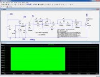
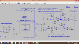
Here is a quick and dirty example: based on a single 4069, it will ramp the current from 0 to 100% in 10s (settable).Sounds interesting,
I haven't done any design on Pulse width modulation so any further information would be useful.
Regards
M. Gregg
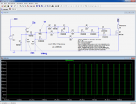
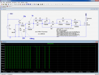
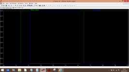
In the sim illustration, time scales have been seriously reduced to save time, but it shows the principles, and the actual values are shown on the schematic
First pic is an overview, second pic is a zoom at the start and third pic is a zoom towards the end.
PS:
With this kind of circuit, you will need a good bypass cap on the 12.6V supply: at least 1000µF, low esr. NO bypass on the filament side, of course.
MOS is given as an example, just any reasonable 50V/10A type will do
Attachments
Last edited:
Here is a quick and dirty example: based on a single 4069, it will ramp the current from 0 to 100% in 10s (settable).
In the sim illustration, time scales have been seriously reduced to save time, but it shows the principles, and the actual values are shown on the schematic
First pic is an overview, second pic is a zoom at the start and third pic is a zoom towards the end.
PS:
With this kind of circuit, you will need a good bypass cap on the 12.6V supply: at least 1000µF, low esr. NO bypass on the filament side, of course.
MOS is given as an example, just any reasonable 50V/10A type will do
Thank's I will have a look,
Should be interesting..
Regards
M. Gregg
I don't see how that helps - to simply PWM doesn't change the peak I in cold filament - which is hugely larger than the PS I limit or we wouldn't have a thread topic
with a actual Switching Power Converter topology, large energy storage L, and input I ripple filtering however you can get relatively efficient Power Conversion - meaning bigger I at the low V cold filament than is drawn from the higher V PS
with a actual Switching Power Converter topology, large energy storage L, and input I ripple filtering however you can get relatively efficient Power Conversion - meaning bigger I at the low V cold filament than is drawn from the higher V PS
Last edited:
Can I have a look at your circuit I assume you are switching the AC?
Regards
M. Gregg
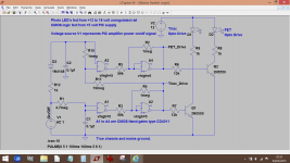
Yes, the triac (opto coupled) is used to initially power the transformer via a limiting resistor. After a short while the triac is shorted via the solid state relay.
When switched off the solid state relay drops out first and then the triac (which you wouldn't need of course).
The logic is reliable and allows for pretty much instantaneous shutdown and restart. You could use that to power a conventional relay to short out a limiting resistor, assuming you could get a suitable value that wouldn't trip your PSU limiter.
Attachments
I don't see how that helps - to simply PWM doesn't change the peak I in cold filament - which is hugely larger than the PS I limit or we wouldn't have a thread topic
Simple arithmetics: at the beginning, if the MOS conducts 4µs over a period of 40µs in a cold filament that has 1/10th of its nominal resistance, the peak current will be 10 times the nominal current, but averaged by the big cap it will look like Inom for the supply; the rms current seen by the filament will be √10 times Inom, thus ~3 times more effective than a plain CCS
input surge currents are usually measured in a few cycles of the AC waveform 10-100 msec or so events.Existing is an NTC at 160 ohms that is shorted by a relay after 10 sec
Im thinking such a long delay of 10s are related to "your timing issues" FWIW older tube audio gear never had a problem with power factor related high surge currents. otherwise consider constant current supply to power heater filaments, I suspect your real concerns are tube life related?
what do you mean trips?The power supply trips on current limit and requires a soft start. Easy.
"the power supply" needs a closer look! sounds like there is little to none surge rating allowed IMO
I need to create a simple circuit that will emulate the NTC circuit without depending on temperature. Like the NTC.
The reason is the NTC even though shorted after start up cannot repeat its function until the equipment cools down, so repeat restarts cannot happen within a short space of time<<problem is repeatability.
since it's relay driven, you can use a simple power resistor in the 1-10 ohms range to limit surges.
Last edited:
- Status
- This old topic is closed. If you want to reopen this topic, contact a moderator using the "Report Post" button.
- Home
- Amplifiers
- Solid State
- I would like a few ideas..