In many writings that can be found on the net, many stated the advantages of having a low value of openloop of a power amp. This when combined with sufficient feedback will result in good reproduction power amp.
First I don't understand this. But after looking at the schematic of "Hi-End" power amp from Motorola, it seems that this low-openloop gain is achieved by putting "just enough" gain on every stage of the power amp.
The gain is roughly can be seen by RC/RE, and in Differential stage and VAS stage, Motorola put combinations of RC/RC that makes the openloop gain is not so big.
The most obvious one is in the VAS, where usually the collector of the VAS transistor dont have RC, but to lower gain, they put RC to ground, so the gain of this VAS is lower than if it hasn't RC.
This low openloop gain theory is also strengthen by Mr.Pass design on Aleph amp. Although it don't have such as RC/RE that can be calculated, but he stated that the mosfet itself has low gain even on open loop.
I have a few question about this theory
1. If I use the output stage of CFP instead of EF, wouldn't that CFP has already gain in it? So it is impossible to have low open loop gain with CFP output?
2. What happens if we have a openloop gain lower than the closed loop gain? (like we design the open loop of 50x, but put the feedback arrangement of 100x), what happens? Will this amp can control the DC offset, inspite of the openloop VS closedloop conditions like above? What will be the gain of the closed loop?
3. What makes the sound tends to be better in low openloop audio power amp? (At least that is what some people said). Is making an openloop as big as possible then limit them by feedback resistors in closed loop is a bad thing? Some designs do this, what is the merits and drawbacks VS the low openloop design? What are the audible difference? Will it influence damping factor or slewrate?
lumanauw said:In many writings that can be found on the net, many stated the advantages of having a low value of openloop of a power amp. This when combined with sufficient feedback will result in good reproduction power amp.
First I don't understand this. But after looking at the schematic of "Hi-End" power amp from Motorola, it seems that this low-openloop gain is achieved by putting "just enough" gain on every stage of the power amp.
The gain is roughly can be seen by RC/RE, and in Differential stage and VAS stage, Motorola put combinations of RC/RC that makes the openloop gain is not so big.
The most obvious one is in the VAS, where usually the collector of the VAS transistor dont have RC, but to lower gain, they put RC to ground, so the gain of this VAS is lower than if it hasn't RC.
This low openloop gain theory is also strengthen by Mr.Pass design on Aleph amp. Although it don't have such as RC/RE that can be calculated, but he stated that the mosfet itself has low gain even on open loop.
I have a few question about this theory
OK..let's go!!!
")
1. If I use the output stage of CFP instead of EF, wouldn't that CFP has already gain in it? So it is impossible to have low open loop gain with CFP output?
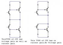
The CFP has current gain in it, as a EF output stage but no voltage gain.
Many people here confuse current gain with voltage gain.
The CFP has the some voltage gain (actualy a litle more) than a EF, but both are less than unity...
The straight answer..yes!! ...it's possible to have a low open loop gain with a CFP output!
2. What happens if we have a openloop gain lower than the closed loop gain? (like we design the open loop of 50x, but put the feedback arrangement of 100x), what happens? Will this amp can control the DC offset, inspite of the openloop VS closed loop conditions like above? What will be the gain of the closed loop
The amp will hve in this case a litlle less than his 50 X gain...negatif feedback can not
increse voltage gain...only steal some
In a trade of for lower distortion ,noise,output impedance and DC off set control.
And in the case of offset control the answer is yes... if you use a capacitor in the lower arm of the feedback voltage divider..in that case the gain become unity at DC and...Bingo.. your DC offset is controled!
3. What makes the sound tends to be better in low openloop audio power amp? (At least that is what some people said). Is making an openloop as big as possible then limit them by feedback resistors in closed loop is a bad thing? Some designs do this, what is the merits and drawbacks VS the low openloop design? What are the audible difference? Will it influence damping factor or slewrate?
This is the eternal question...feedback is a good or a bad thing??
Feedback make the output be similar to the input...(see the null test)...some people don't like acuracy and prefer euphonic colorations... feedback is a powerfull tool in electronic design.
Yes the feedback will influence the damping factor...slew rate is more dependent of the design of the amp...
Thanks, for the explenation. But I'm not clear about CFP output. Maybe it is a different meaning or different schematic for me. For me CFP is built by 2 transistor, one is smaller transistor, which its emitor is to output, and its collector (Usually about 100 ohm) feds the big transistor. The emitor of this big transistor goes to VCC rail, and the collector goes to output. Since the output of this big transistor is from its collector, so it must have voltage gain, more than unity.
Is it CFP don't have voltage gain? In many of QSC audio power amp, the rail is more than +/-100V, but the differential is using opamp (only+/-15V supply) combined with CFP output. Both voltage and current gain are in this CFP output, while the opamp is only to fix the gain factor.
Is it CFP don't have voltage gain? In many of QSC audio power amp, the rail is more than +/-100V, but the differential is using opamp (only+/-15V supply) combined with CFP output. Both voltage and current gain are in this CFP output, while the opamp is only to fix the gain factor.
lumanauw said:Thanks, for the explenation. But I'm not clear about CFP output. Maybe it is a different meaning or different schematic for me. For me CFP is built by 2 transistor, one is smaller transistor, which its emitor is to output, and its collector (Usually about 100 ohm) feds the big transistor. The emitor of this big transistor goes to VCC rail, and the collector goes to output. Since the output of this big transistor is from its collector, so it must have voltage gain, more than unity.
Is it CFP don't have voltage gain? In many of QSC audio power amp, the rail is more than +/-100V, but the differential is using opamp (only+/-15V supply) combined with CFP output. Both voltage and current gain are in this CFP output, while the opamp is only to fix the gain factor.
The "trick" is that the CFP pair has a built-in local feedback that
takes away all the voltage gain. you still have the current gain.
Since the collector of the "output device" is tied to the emitter
of the input "device", any "tendecy to voltage amplification" in
the output device will give a "tendency to reduce" the Vbe of
the input device, and the net result is that you get no voltage
gain, but current gain and improved linearity etc.
I think a reasonable way to think of the CFP is as an emitter
follower with a current booster.
Note that an ordinary emitter follower also has local feedback,
but the CFP usually has a much higher loop gain.
For your seccond question, it is hard to say anything definite
without a schematic, but as you describe it there must be some
voltage amplification stage between the op amp and the output
CFPs.
Commentable Thoughts
Hey Lumanauw
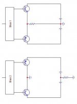
Ampman has illustrated ur question on the diagram.
Check it out.
lumanauw said:Thanks, for the explenation. But I'm not clear about CFP output. Maybe it is a different meaning or different schematic for me. For me CFP is built by 2 transistor, one is smaller transistor, which its emitor is to output, and its collector (Usually about 100 ohm) feds the big transistor. The emitor of this big transistor goes to VCC rail, and the collector goes to output. Since the output of this big transistor is from its collector, so it must have voltage gain, more than unity.
Is it CFP don't have voltage gain? In many of QSC audio power amp, the rail is more than +/-100V, but the differential is using opamp (only+/-15V supply) combined with CFP output. Both voltage and current gain are in this CFP output, while the opamp is only to fix the gain factor.
Hey Lumanauw
Ampman has illustrated ur question on the diagram.
Check it out.
Attachments
One of the questions is: does lower open loop gain sound better?
Lets look at high open loop gain. Generally, that is good, because it allows strong feedback which means low THD, low offset, very high damping factor, immunity from drifting and component aging. I think most people will agree that in itself these are desirable properties.
The problem is that high loop gain comes from almost always with largish phaseshifts, so when you DO apply the strong feedback, the large phase shift at higher frequencies causes instability. To tame them, you have to roll of the freq response open loop to make sure it is less than 1 at the freq where the phase shift reaches 180 degrees. (There are opamps that start open loop roll off at 10Hz). This then again means that the strong feedback is no longer effective at higher frequencies. Also, the means to roll of the gain in itself can have bad effects like limiting slewrate.
So how to avoid this? Use low open loop gain, meaning less phaseshift (generally) and accept less effective feedback, that is however constant across most of the freq range. The trick here is to find a fine compromise to avoid the pitfalls of high feedback and still get the benefits from feedback itself.
Whether the low open loop gain amp sounds better is in the end depending on how clever the designer can balance these conflicting requirements. Important is the ability to construct a low open loop gain amp that is linear in itself, before the application of feedback.
BTW, a CFP pair is a high open loop gain stage. It is the (100%) feedback that reduces the closed loop gain to unity.
Jan Didden
janneman said:[...](There are opamps that start open loop roll off at 10Hz).
Bug or feature?
I'm all fine with this behaviour, if it comes with high enough open loop gain at 20kHz. At least the pase of this constant over the audio range.
Instead of gasping of low ol gains, just state that it is an integrator. Sounds much better.
Regards,
Peter Jacobi
Yes !! Your descrition of two transistors ,one smaller feeding one big output is a CFP...and yes it don't have voltage gain!lumanauw said:Thanks, for the explenation. But I'm not clear about CFP output. Maybe it is a different meaning or different schematic for me. For me CFP is built by 2 transistor, one is smaller transistor, which its emitor is to output, and its collector (Usually about 100 ohm) feds the big transistor. The emitor of this big transistor goes to VCC rail, and the collector goes to output. Since the output of this big transistor is from its collector, so it must have voltage gain more than unity
Thats is another case...if that case the emiters of the "smaller" resistor don't connect to the output (and colector of the big transistor). but are connected to a voltage divider from output and ground....Is it CFP don't have voltage gain? In many of QSC audio power amp, the rail is more than +/-100V, but the differential is using opamp (only+/-15V supply) combined with CFP output. Both voltage and current gain are in this CFP output, while the opamp is only to fix the gain factor
Usualy in this last case the gain of the output stage is 2 or 3 and the op amp can swing the full 100 volts at the output..
The voltage divider in that case do all the diference!!
Here you will find a exemple!
http://www.audiofanatic.it/Schemi/Tipo/Stato_solido/finali/pic_finaliSS/120W_MOS_IRF9540_540.jpg
pjacobi said:
Bug or feature?
I'm all fine with this behaviour, if it comes with high enough open loop gain at 20kHz. At least the pase of this constant over the audio range.
Instead of gasping of low ol gains, just state that it is an integrator. Sounds much better.
Regards,
Peter Jacobi
Feature, of course!
And yes, it's an integrator. In fact, most audio amps basically are integrators.
Jan Didden
Tube_Dude said:
Yes !! Your descrition of two transistors ,one smaller feeding one big output is a CFP...and yes it don't have voltage gain!
Thats is another case...if that case the emiters of the "smaller" resistor don't connect to the output (and colector of the big transistor). but are connected to a voltage divider from output and ground....
Usualy in this last case the gain of the output stage is 2 or 3 and the op amp can swing the full 100 volts at the output..
The voltage divider in that case do all the diference!!
Basically, a CFP is a two stage amp with open loop voltage gain. The closed loop gain is set with the two resistors as you say. The special case where one of the resistors is zero gives 100% neg feedback and reduces the voltage gain to close to one. But the basic circuit is always the same.
Jan Didden
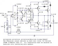
"Is it CFP don't have voltage gain? In many of QSC audio power amp, the rail is more than +/-100V, but the differential is using opamp (only+/-15V supply) combined with CFP output. "
http://www.diyvideo.com/forums/attachment.php?postid=182299
The schematic shows the Hafler Transnova, the QSC uses the same grounded output stage.
Another way to build it would be to swap ground and the center tap on the transformer (so it looks like a normal amplifier) and run the ground reference for the opamp ±15V on the amplifier positive output (this is called suspended supply operation).
djk said:
The schematic shows the Hafler Transnova, the QSC uses the same grounded output stage.
I think there are an ATC amp that use the same technology.
If memory serves...
With the method of QSC amp works (output from the CT of the transformer) it is possible for us to make all the stages before the transformer (from the differential, VAS, output stage) not to have ANY voltage gain at all. Both the current and voltage gain are in the transformer itself.
Could this be considered a low openloop gain, since all the electronics dont have any gain is possible? Or this is exactly not low openloop gain, since the gain in the transformer system is indeed very big?
(we only have to drive + and -0.6VDC on final transistor to get full max swing of +-VCC. If the VCC is 1000V, we can obtain this voltage only by driving the final transistor 0.6V, because it is inverted by the CT transformer itself.
Is there any audible excellence in this kind of configuration, or is it tends to be worse than ordinary amp? Or is it producing the same output quality?
One more question about this configuration. In ordinary amp, we use bank of caps (10.000uF per rail). How important this cap-bank in this kind of power amp, since we modulate the transformer? Will the cap only 100uF sufficient in this configuration, or is it still need the same 10.000uf?
Attachments
If you connect the load between the point E and the sources of the FETS, you have a traditional amp except that the ground connection is moved to the other side of the load.
If you have the feedback polarities correct, I don't see any reason why the quality of the sound should be different, in principle.
Jan Didden
If you have the feedback polarities correct, I don't see any reason why the quality of the sound should be different, in principle.
Jan Didden
It is an advantage, but minor in my view. The downside is that the power supplies float up and down with the signal, which may give all sorts of problems with parasitic capacitances.
There actually are several patents to this and similar topologies, all claiming great benefits. Transnova is one IIRC. It is a way to discern yourself from all the other "standard" amps on the market and as such may be a valuable marketing tool. Most of the times these schemes are picked apart in the trade press.
Jan Didden
Re: Commentable Thoughts
Actually Ampman, the circuit on the left is a follower,
as it has unity gain via local feedback, so it does not have
voltage gain as seen by the outside world.
amp_man_1 said:Ampman has illustrated ur question on the diagram.
Check it out.
Actually Ampman, the circuit on the left is a follower,
as it has unity gain via local feedback, so it does not have
voltage gain as seen by the outside world.
lumanauw said:In many writings that can be found on the net, many stated the advantages of having a low value of openloop of a power amp. This when combined with sufficient feedback will result in good reproduction power amp.
IMHO this is not an issue. Try to obtain the best possible linearity of every stage (before the NFB is applied). Then after applying negative feedback (global) you will get perfect sonic result. One of the biggest mistakes is to try to compensate non-linearities (cross-over, turn-on-offs etc.) only by global NFB.
- Status
- This old topic is closed. If you want to reopen this topic, contact a moderator using the "Report Post" button.
- Home
- Amplifiers
- Solid State
- Low openloop gain amplifier