Do not connect a speaker when you are still trying to test your amplifier.
Most testing is done with the output feeding an open circuit.
Later you can use a dummy resistive load and later still add a paralleled capacitor, but still no speaker !
Do use a Mains Bulb Tester to minimise damage due to a wiring error.
Most testing is done with the output feeding an open circuit.
Later you can use a dummy resistive load and later still add a paralleled capacitor, but still no speaker !
Do use a Mains Bulb Tester to minimise damage due to a wiring error.
Hi guys,
I have managed to create new PCBs (the old ones were in a bad condition due to multiple re-soldering) with brand new parts. This time the situation is ever worse: the voltage at the output is 10.44V and turning RV100 from end-to-end does not change it. The only change is at the testing point at R111 - from 5.55V to 7.1V. The emitter voltage of TR100 (BC560) is 9.08V. During the measurements TR105 became warm. The base voltage of TR103 (2N5322) is 11.35V.
Thanks in advance for your suggestions and clues where to start from")
I have managed to create new PCBs (the old ones were in a bad condition due to multiple re-soldering) with brand new parts. This time the situation is ever worse: the voltage at the output is 10.44V and turning RV100 from end-to-end does not change it. The only change is at the testing point at R111 - from 5.55V to 7.1V. The emitter voltage of TR100 (BC560) is 9.08V. During the measurements TR105 became warm. The base voltage of TR103 (2N5322) is 11.35V.
Thanks in advance for your suggestions and clues where to start from
Hi Mooly,
Below are the measurements:
TR100
E= 9.23V
B= 8.62V
C= 9.22V
TR101
E= 50.3mV
B= 455mV
C= 1.3V
TR102
E= 648mV
B= 1.3V
C= 9.95V
TR103
E= 10.7V
B= 11.24V
C= 66.2V
TR104
E= 10.59V
B= 9.97V
C= 555mV
TR105
E= 66.7V
B= 66.2V
C= 10.85V
TR106
E= 34V
B= 557mV
C= 10.85V
TR107
E= 10.14V
B= 10.87V
C= 11.33V
TR1
E= 10.76V
B= 10.75V
C= 66.7V
TR2
E= 26mV
B= 36.2V
C= 10.74V
Thanks. I'll have a study later. Nothing obvious jumps out apart from the fact you mentioned TR105 getting warm and yet TR1 appears off (no base emitter differential and so implying no voltage across R123).
Do you have a scope ? I wondered if the amp could be oscillating and so the DC voltages are not entirely accurate. Just a thought.
If not then we can still prove if its oscillating or not by you connecting an R/C network from L100 to ground (say 100k and 10uf) and checking the voltage across the cap equals the voltage you see on L100. If its oscillating then they will be very different.
TR2 & TR106 have a damaging Vbe. Recheck these measurements.
TR1 appears to be completely off.
TR101 has an unusually low Vbe
All the others show a Vbe in the normal range of 550mV to 700mV
Check that the NPN transistors have their Base voltage approximately 600mV higher than the Emitter voltage.
Check that the PNP transistors have their Base voltage approximately 600mV lower than the Emitter voltage.
Yes, something is amiss around TR2 as Andrew mentions.
An NPN B-E junction can't support more than around 800mv forward biased. Also, you have that same voltage on the emitter of TR106 which suggests that R127 also has that voltage present which would instantly burn it out.
I would recheck around there because there is nowhere that such a high voltage could come from based on your other readings.
For example, TR106 emitter at 34 volts suggests that voltage or higher has to be present on either the collector or base of TR106 and/or the collector of TR2. There is nowhere else it can come from apart from either a board layout error or readings being affected by instability.
Do the check I mentioned with a resistor and cap and see what result you get.
Are the boards that you made following the original layout ?
Hi guys, I am sorry (the measurements were taken at 1am) and I misread the voltage readings:
TR106
E= 34mV
B= 560mV
C= 10.74V
TR2
E= 26mV
B= 34mV
C= 10.76V
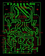
Also, I do have a scope and there is no oscillation at the output. The PCB I sketched is "inspired" by the original layout. The only changes I made are around the 0.3 ohms resistors since the ones I had a too large:
TR106
E= 34mV
B= 560mV
C= 10.74V
TR2
E= 26mV
B= 34mV
C= 10.76V
Also, I do have a scope and there is no oscillation at the output. The PCB I sketched is "inspired" by the original layout. The only changes I made are around the 0.3 ohms resistors since the ones I had a too large:
Attachments
No problem
So it appears the output transistors are not conducting, but more importantly the midpoint voltage is a long way in error.
Here is what I would do:
1/ Make 100% certain the bias current preset is turned to give minimum current. That means RV101 has to be set for maximum resistance to ensure TR107 is fully on.
2/ Do a quick and dirty test by removing R130 (150k). This should force the output to the positive rail and you should measure around 65 volts on the output.
If that doesn't happen, and the output voltage is low, then remove TR102 whilst still keeping R130 removed.
This splits the circuit in two and removes the feedback and front end of the circuit. The output must now rise to the supply voltage. If it doesn't then there is a problem in the driver/output section that should)) be fairly easy to trace.
As the circuit has been totally rebuilt, it is worth checking all the correct values are where they should be.
So it appears the output transistors are not conducting, but more importantly the midpoint voltage is a long way in error.
Here is what I would do:
1/ Make 100% certain the bias current preset is turned to give minimum current. That means RV101 has to be set for maximum resistance to ensure TR107 is fully on.
2/ Do a quick and dirty test by removing R130 (150k). This should force the output to the positive rail and you should measure around 65 volts on the output.
If that doesn't happen, and the output voltage is low, then remove TR102 whilst still keeping R130 removed.
This splits the circuit in two and removes the feedback and front end of the circuit. The output must now rise to the supply voltage. If it doesn't then there is a problem in the driver/output section that should
)) be fairly easy to trace.As the circuit has been totally rebuilt, it is worth checking all the correct values are where they should be.
That's a slightly unexpected result. Removing TR102 and the output rising is correct but it should also alter when R130 is removed.
I'm assuming you've replaced all the parts with new. First thing has to be a double check on all the passives and that they are the correct value. Particularly the resistors around the preset.
Lets try something different to try and get a handle on this.
Refit R130 and TR102 and confirm the fault is still present.
TR100 collector is high at the 9 volts you measured. That voltage should be turning on TR101 and so pulling the collector of TR101 down and in fact that seems to be happening.
That in turn should turn off TR102 as it pulls the base of TR102 to ground which would then allow the output voltage to rise.
Removing TR102 did cause the output to rise.
So, looking around there it seems TR102 is either conducting a little when it shouldn't or there is some problem with the component values (or TR102... make sure it is a suitable NPN correctly fitted).
A base emitter junction reversed biased does actually drop around 7 to 9 volts give or take (its device specific). So if TR102 were incorrectly fitted it could operate as zener and so fix the output at this 10 volts you are seeing. So definitely check around that device and make sure its an NPN fitted properly.
Do both your boards have the same problem ?
Lets work through those voltage readings then and see what shows up.
You have 9 volts on TR100 collector and yet 'only' 0.45 on the base of TR101. I would really expect to see TR101 fully saturated and with around 650 to 750mv on the base.
It is worth confirming the resistors around there are OK (correct values for R105, R107 and R109). Also make sure TR101 is good and has decent forward gain.
TR101 is specified as a BC109 which was a really high gain transistor back in the day. Was it a BC109C ?
For some reason it doesn't seem to be in the parts list of my manual.
I must admit, this is a very lame mistake - R105 measured 47k, instead of 4.7k! (checked the packaging of the spare resistors - incorrectly marked as 4.7k by the local branch of Comet electronics). After the replacement with correct value for R105, the output was adjustable (33.5V). But the happines was short - after turning it off and on again (to connect a speaker) the 0.5A fuse (installed only fo testing purposes) blew up. It was 3:00am last night, so I desided to put it on hold and share the news
It happens and at least the fault finding theory pointed to a problem in that area.
The next step, assuming the output transistors have survived, would be to force a zero bias condition by linking out TR107. The amp should then adjust and run normally but with zero bias and so a little higher distortion.
And always use a bulb tester when experimenting. It can save major blow-ups.
and at least the fault finding theory pointed to a problem in that area.The next step, assuming the output transistors have survived, would be to force a zero bias condition by linking out TR107. The amp should then adjust and run normally but with zero bias and so a little higher distortion.
And always use a bulb tester when experimenting. It can save major blow-ups.
- Status
- This old topic is closed. If you want to reopen this topic, contact a moderator using the "Report Post" button.
- Home
- Amplifiers
- Solid State
- Quad 303 Power Amplifier - Left Channel Distorted