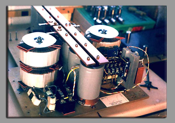
DC100 amp that I built in 1991 from an Old Colony kit. A few years ago I changed out the main P/S caps after the hum coming through the speakers became audible from my listening chair. The original caps were 8 of the large screw terminal Sprague 10,000 uf. I used 8 Cornel Dublier 10,000 uf snap-in style on 2 filter PCB's. I did not bother yet to do the other 'lytic caps on the boards or the ones point-to-point soldered near the output devices. They are an unknown model from Rubycon 47 uf and 100 uf 100v. What would be a good replacement for those? And any chance someone has the schematic for this amp? I lost the original documentation.
Before:
After:
Before:
An externally hosted image should be here but it was not working when we last tested it.
After:
An externally hosted image should be here but it was not working when we last tested it.
I would recommend much much more capacitance, if you can swing it and your transformer is capable.
Also the ground should be at a single point, preferably at the actual electrical center of the ground connections of the cap bank - all grounds should go to that spot, or more properly to a suitably high current tab or solder point connected there.
In your original layout, I'd have turned the two cap banks 90 degrees and put the ground center between the two ground planes.
You can likely safely leave the caps near the output devices.
The amp will benefit from the replacement of the output zobel coil with one done up from
substantially heavier wire - this requires some "drilling and blasting" on the PCB, as you will not be able to fit it into the same two holes - one, not two. Number 10wire is a good bet. You can get away with a few less turns.
If you are unable to find the schematic online, I may be able to find one somewhere on a computer around here. The amp was an article in Audio Amateur, so that is one way to find it.
4 10mF to each amp seems OK to me.
That gives +-20mF per channel and is good for bass down to 20Hz.
Bear,
why do you suggest
That gives +-20mF per channel and is good for bass down to 20Hz.
Bear,
why do you suggest
I would recommend much much more capacitance,
Unless you want multi-hundred watts at low (2-4ohms) impedances, the values you are using now are more than adequate. Anyway, your transfo will limit the charge current, so increasing cap values beyond that makes not much sense. If you want to gild the lily, you might try to replace your rectifiers with ultrafast recovery ones,(NTE 597, BYW 29-200, etc.) and bypass the main filter caps with a few uF's worth of good quality film types (MKP or MKC).
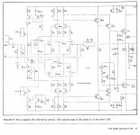
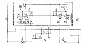
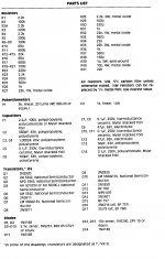
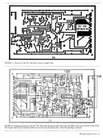
Here you go.And any chance someone has the schematic for
---Gary
Attachments
Thank you all for looking at this.
Gary, much appreciated! I could not find them anywhere on the Internet.
Dragonweed, I'm now using MUR1520 diodes in the rectifier bridges, and a CRC P/S filter arangement:
Bear, I was planning to up the capacitance to 4 x 33,000 uf Epcos since now I'm using 1000 VA transformer instead of 2 wimpy 225 VA torroids. So, no longer a dual mono setup, but either channel now has access to 1000VA instead of 225. It has more "authority" now.
Gary, much appreciated! I could not find them anywhere on the Internet.
Dragonweed, I'm now using MUR1520 diodes in the rectifier bridges, and a CRC P/S filter arangement:
An externally hosted image should be here but it was not working when we last tested it.
Bear, I was planning to up the capacitance to 4 x 33,000 uf Epcos since now I'm using 1000 VA transformer instead of 2 wimpy 225 VA torroids. So, no longer a dual mono setup, but either channel now has access to 1000VA instead of 225. It has more "authority" now.
An externally hosted image should be here but it was not working when we last tested it.
If you want to increase the filter bank as you indicated, with THAT transfo, (isn't it a bit too close to your driver board? Hum, stray field?)) then you will likely need an inrush current limiter unless you want to reset your home's circuit breakers every time you turn it on....

If you want to increase the filter bank as you indicated, with THAT transfo, (isn't it a bit too close to your driver board? Hum, stray field?)) then you will likely need an inrush current limiter unless you want to reset your home's circuit breakers every time you turn it on....
I installed a soft-start board when I did the cap replacement. More recently I installed the bigger xformer and high-speed rectifiers. Yes, it is close to the left-channel board but I don't have a hum issue. There is a slight 120 Hz buzz with your ear about a foot from the tweeter. Probably would have to eliminate the rat's nest of wiring between the driver boards and output stages to lower the noise level further.
An externally hosted image should be here but it was not working when we last tested it.
Which amp next?
Gary, I'm guessing you own or owned at one time a DC100. What do you have now and how does the Borbely compare?
I'm looking at building a Pass F5T, Honey Badger, DX Blame, or a Symsym. I haven't been able to decide yet which one to go with.
Thanks!
Richard
Here you go.
---Gary
Gary, I'm guessing you own or owned at one time a DC100. What do you have now and how does the Borbely compare?
I'm looking at building a Pass F5T, Honey Badger, DX Blame, or a Symsym. I haven't been able to decide yet which one to go with.
Thanks!
Richard
Looking at the schematic, impedance balance strikes me as rather non-ideal, at ~4k4 vs. ~100R. I am not sure how sensitive this peculiar push-pull input stage might be to this, but still.
It's an interesting circuit for sure, hats off to Mr. Borbely. I wonder how he gets much of any transconductance from the input FETs, their currents must surely be quite low?
It's an interesting circuit for sure, hats off to Mr. Borbely. I wonder how he gets much of any transconductance from the input FETs, their currents must surely be quite low?
Richard,Gary, I'm guessing you own or owned at one time a DC100. What do you have now and how does the Borbely compare?
I bought the boards from Audio Amateur years ago but never actually built the amp. Just a couple of years ago I sold the boards here on diyaudio and someone finished them up.
I did build a later Borbely amp, the DC-102 which is very fine sounding. These days I'm almost exclusively into tubes using either classic older push-pull amps (HK Citation, McIntosh, Scott) or home brew single ended (2A3 or VT25 or 6CB5). I've got an old Threshold S/200II amp which is my go to solid state amp when I want to try that out or when I decide to biamp. Solid state below 500hz and tubes above is a very nice combo.
---Gary
I installed a soft-start board when I did the cap replacement. More recently I installed the bigger xformer and high-speed rectifiers. Yes, it is close to the left-channel board but I don't have a hum issue. There is a slight 120 Hz buzz with your ear about a foot from the tweeter. Probably would have to eliminate the rat's nest of wiring between the driver boards and output stages to lower the noise level further.
Have you tried separating the low current supplies from the high ones. Regulating the voltage amp stages would probably improve things. How much you would have to say.
The Goldmund uses a cap multiplier, which is the simplest you can get. But I would certainly use separate diodes and caps for the low current stages.
There was an article in the old The Audio Amateur where the first Borbely amp project published there was modified in stages, measuring noise and distortion after each mod. The final one was a regulated supply for the low current stages, and things measured a lot better.
Borbely himself added Kit Ryan style regulators for low current stages, when he updated his MOSFET amp designs in '93.
Even using something like a 3x7 regulator, protected with zener diodes, should work great. Increasing the voltage for that regulation might be a good idea too. You can do that adding more thin wire windings to the transformer or using cap diode doubler, as used by Nelson Pass on his A75 amp.
Last edited:
- Status
- This old topic is closed. If you want to reopen this topic, contact a moderator using the "Report Post" button.
- Home
- Amplifiers
- Solid State
- Cap upgrade for Borbely DC100